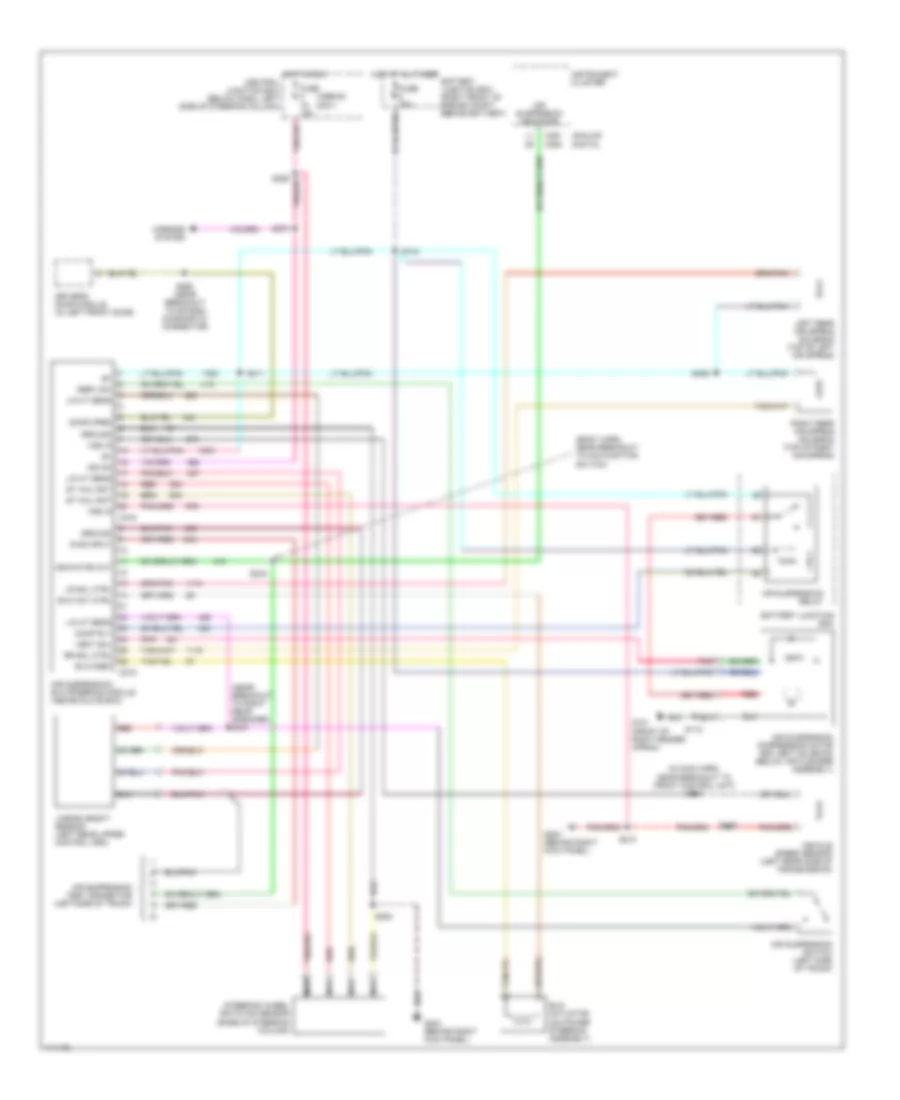
ELECTRONIC SUSPENSION
Electronic Suspension Wiring Diagram for Ford Crown Victoria 2000
List of elements for Electronic Suspension Wiring Diagram for Ford Crown Victoria 2000:
- (1999-00) (2001)
- (body harn, near breakout to malfunction switch)
- (in main harn, near breakout to front control unit) s247
- (near breakout to right rear speaker) s431
- Air suspension compressor motor and vent solenoid (below air cleaner assembly)
- Air suspension indicator
- Air suspension relay
- Air suspension switch (left side of trunk)
- Air suspension test connector (left side of trunk)
- Air suspension/ evo steering module (above glove box)
- Analog digital
- Battery junction box
- Battery junction box (right front of engine compt, behind battery)
- C215
- C216
- C251 c254
- Central junction box (below dash, left side of steering column)
- Comp rly
- Diag input
- Door open
- Driver's door module (in left front door)
- Evo act ctrl
- Evo actuator (on power steering assembly)
- Evo fdbk
- Fuse 15a
- Fuse 30a
- G101 (front of right fender apron)
- G203 (behind right kick panel)
- Ground
- Hot at all times
- Hot in run
- Ign on
- Indicator out
- Instrument cluster
- Left rear air spring solenoid (top of left air spring)
- Lin ht sens
- Linear height sensor (left rear upper control arm)
- Lr sol ctrl
- Mirrors system
- Nca
- Pnk
- Red
- Right rear air spring solenoid (top of right air spring)
- Rr sol ctrl
- S105
- S112
- S144
- S208
- S210
- S234
- S268 (near breakout to air bag diagnostic connector)
- S274
- S406
- S411
- Serv sw
- St whl rot
- Steering wheel rotation sensor (base of steering column)
- Vehicle speed sensor (left rear side of transmission)
- Vent sol
- Vss in
 English