ELECTRONIC SUSPENSION
Electronic Suspension Wiring Diagram (1 of 2) for Ford Explorer 1995

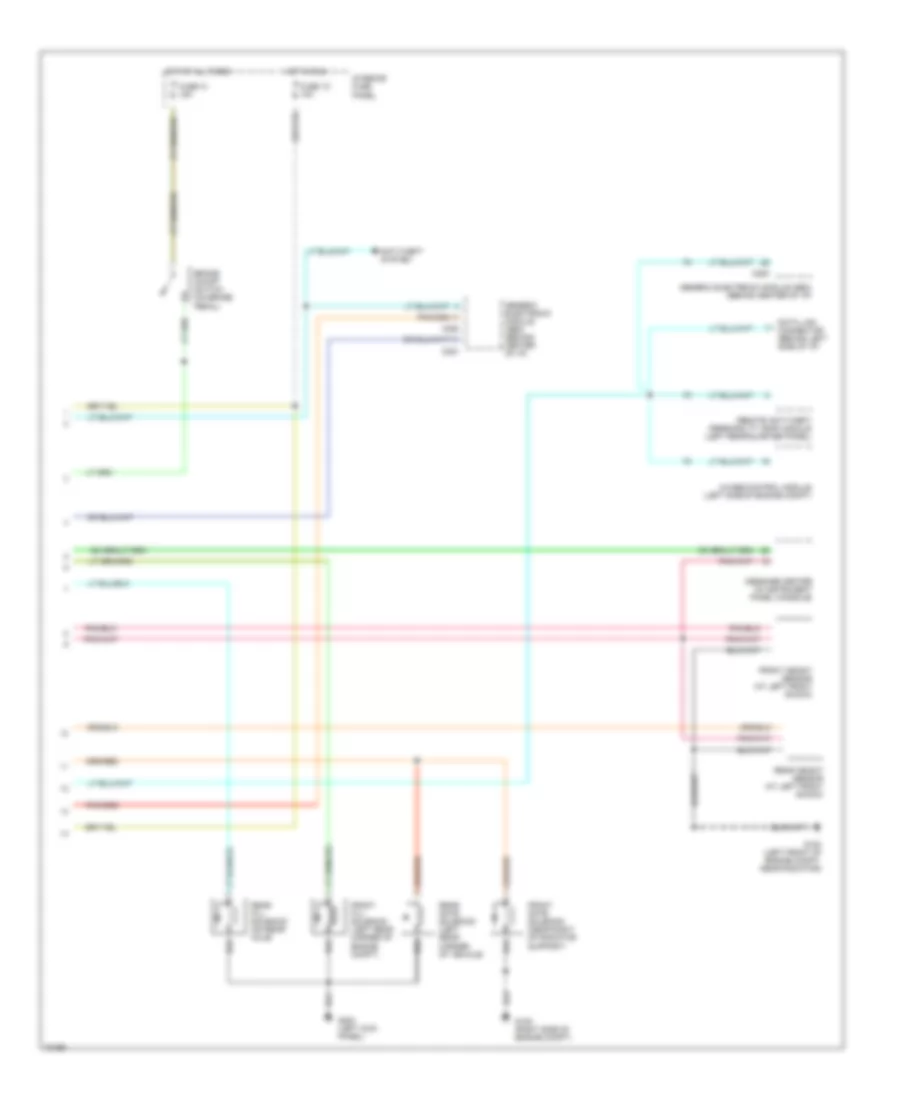
List of elements for Electronic Suspension Wiring Diagram (1 of 2) for Ford Explorer 1995:
- (left rear corner of engine compt, at g104 fender apron)
- 4x4 high sig
- 4x4 low sig
- Air ride control (arc) module (left center of i/p)
- Air ride control compressor assembly (at rear of vehicle)
- Air ride control off/on switch (rear of vehicle)
- Air ride control relay (in auxiliary relay #3)
- Arc accel sig
- Arc comp rly
- Arc off/on sw
- Brake on/off sw
- C2000
- C2001
- Comp vent sol
- Door ajar in
- Engine controls system
- Front fill sol
- Front height sen
- Frt & rr gate sol
- Fuse 18 15a
- Fuse 3 50a
- G104 (left rear corner of engine compt, at fender apron)
- G105 (right side of engine compt)
- G1oo (left rear of engine compt, near radiator)
- G200 (left kick panel)
- Gnd
- Height sen power
- Hot at all times
- Iso link
- Left front shock actuator (at left front shock)
- Left rear shock actuator (at left rear shock)
- Lf shock actuator
- Lf shock pos fb
- Lr shock actuator
- Lr shock pos fb
- Nca
- Pcm accel sig
- Pnk
- Power (hot in run)
- Power distribution box
- Powertrain control module (pcm) (right rear of engine compartment)
- Rear fill sol
- Rear height sen
- Red
- Rf shock actuator
- Rf shock pos fb
- Right front shock actuator (at right front shock)
- Right rear shock actuator (at right rear shock)
- Rr shock actuator
- Rr shock pos fb
- Steering rate sensor (in steering column)
- Steering sen a
- Steering sen b
- Vehicle speed sensor (on trans- mission)
- Vss (+)
- Warning sig
Electronic Suspension Wiring Diagram (2 of 2) for Ford Explorer 1995
List of elements for Electronic Suspension Wiring Diagram (2 of 2) for Ford Explorer 1995:
- 4wabs control module (left side of engine compt)
- Anti-theft system
- Brake on/off switch (on brake pedal)
- C280
- C281
- C282
- Data link connector (behind left side of i/p)
- Front fill solenoid (left rear corner of engine compt)
- Front gate solenoid (near right of radiator support)
- Front height sensor (at left front shock)
- Fuse 13 15a
- Fuse 1o 10a
- G100 (left front of engine compt, near radiator)
- G105 (right side of engine compt)
- G200 (left kick panel)
- Generic electronic module (gem) (behind center of i/p)
- Hot at all times
- Hot in run
- Interior fuse panel
- Message center (in instrument panel console)
- Rear fill solenoid (on rear axle)
- Rear gate solenoid (left rear corner of vehicle)
- Rear height sensor (at left front shock)
- Remote anti-theft personality (rap) module (left rear quarter panel)