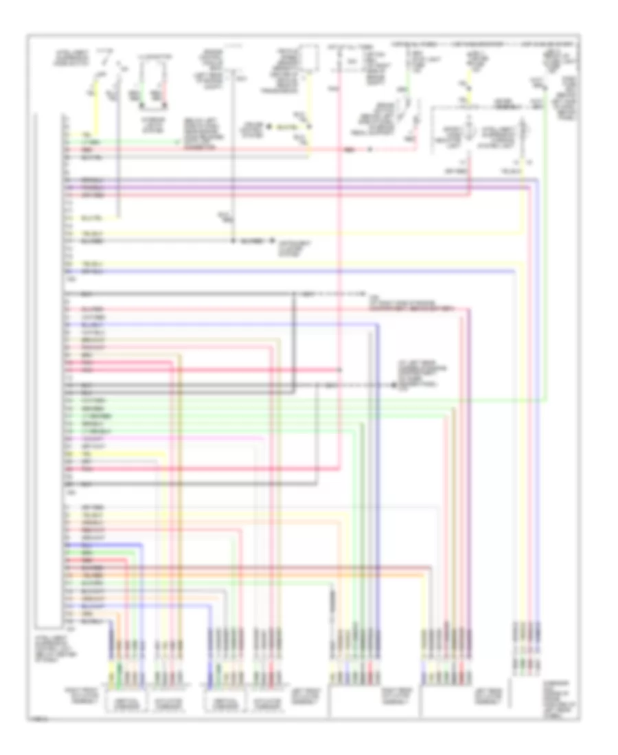
ELECTRONIC SUSPENSION
Electronic Suspension Wiring Diagram for Isuzu Rodeo S 2003
List of elements for Electronic Suspension Wiring Diagram for Isuzu Rodeo S 2003:
- (at left rear corner of engine compartment, on inner fender panel) c16
- (below left side of dash, near engine hood release) data link
- (left rear of engine
- 30a
- Actuator g-sensor
- Brake switch (behind left side of dash, on brake pedal support)
- C36 (at right side of engine compartment, behind battery)
- C50
- C51
- C52
- Cb-11 meter fuse 15a
- Cb-14 back up/ turn light fuse 15a
- Cb-6 stop light fuse 15a
- Center of vehicle, rear of transmission)
- Compt)
- Connector
- Cruise control system
- Dash fuse box (behind left side of dash, behind panel)
- E-21
- Engine control module (ecm)
- G-sensor (g-3) (inside of frame, forward of left rear wheel)
- Hot at all times
- Hot in on or start
- I-1
- I-9
- Illumination
- Instrument cluster system
- Intelligent suspension control unit (below center of dash)
- Intelligent suspension mode switch
- Intelligent suspension warning system light
- Interior lights system
- Left front actuator assembly
- Left rear actuator assembly
- Meter assembly
- Off
- Option box (at right side of engine compt)
- Pnk
- Red
- Right front actuator assembly
- Right rear actuator assembly
- Sport mode indicator light
- Vehicle speed sensor (beneath
- Vertical g-sensor
 English