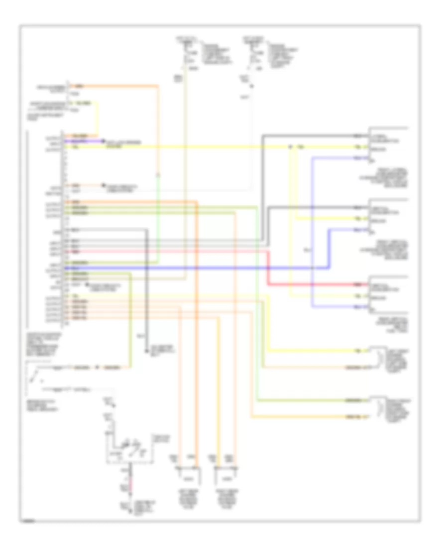
ELECTRONIC SUSPENSION
Electronic Suspension Wiring Diagram for Jaguar XJR 2003
List of elements for Electronic Suspension Wiring Diagram for Jaguar XJR 2003:
- (center of dash, on firewall) fc17
- (i) acc
- (ii) run
- (on center of firewall) em17
- Adaptive damping control module (next to passenger side blower/ glove box assembly)
- Adaptive damping warning input
- Anti-lock brakes system
- Brake switch (on brake pedal bracket)
- Computer data lines system
- Data
- Em20
- Engine compartment fuse box (left front of engine compt)
- Engine management fuse box (left side of engine compt)
- Fc24
- Fc25
- Front lateral accelerometer (in engine compartment, in control module enclosure)
- Front vertical accelerometer (in engine compartment, in control module enclosure)
- Fuse 10a
- Fuse 20a
- Gnd
- Ground
- Hot at all times
- Hot in run & start
- Ignition
- Ignition switch
- Input
- Lateral acceleration
- Left front damper solenoid (left side of engine compt)
- Left rear damper solenoid (on rear axle)
- Ls6
- Major instrument pack
- Nca
- Off (0)
- Output
- Rear vertical accelerometer (below fuel tank)
- Red
- Right front damper solenoid (right side of engine compt)
- Right rear damper solenoid (on rear axle)
- Start (iii)
- Vehicle speed output
- Vertical acceleration
 English