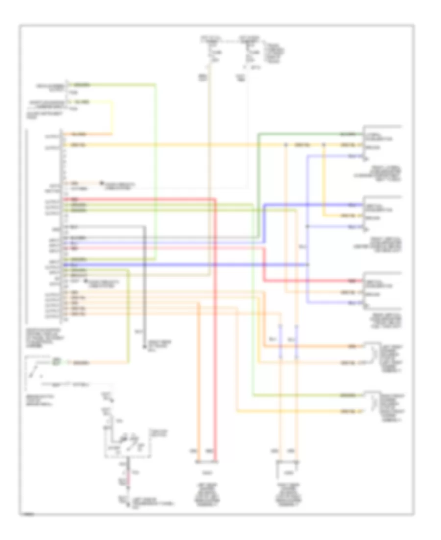
ELECTRONIC SUSPENSION
Electronic Suspension Wiring Diagram for Jaguar XKR 2006
List of elements for Electronic Suspension Wiring Diagram for Jaguar XKR 2006:
- (i) acc
- (ii) run
- (left side of transmission tunnel) fc3
- (right rear of trunk)
- Adaptive damping control module (in trunk, adjacent to electrical carrier)
- Adaptive damping warning input
- Brake switch (top of brake pedal)
- Bt13
- Bt2
- Computer data lines system
- Data
- Fc25
- Fc26
- Fc4
- Front lateral accelerometer (in engine compartment, next to ecm)
- Front vertical accelerometer (center console, behind ice head unit)
- Fuse 20a
- Fuse 5a
- Gnd
- Ground
- Hot at all times
- Hot in run & start
- Ignition
- Ignition switch
- Input
- Lateral acceleration
- Left front damper solenoid (top of left front damper assembly)
- Left rear damper solenoid (top of left rear damper assembly)
- Major instrument pack
- Nca
- Off (0)
- Output
- Rear vertical accelerometer (trunk, below fuel tank unit)
- Red
- Right front damper solenoid (top of right front damper assembly)
- Right rear damper solenoid (top of right rear damper assembly)
- Start (iii)
- Trunk fuse box (at right side of trunk)
- Vehicle speed output
- Vertical acceleration
 English