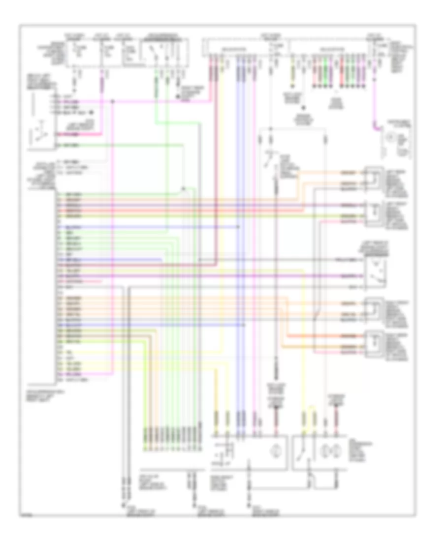
ELECTRONIC SUSPENSION
Electronic Suspension Wiring Diagram for Land Rover Range Rover HSE 1998
List of elements for Electronic Suspension Wiring Diagram for Land Rover Range Rover HSE 1998:
- (below left front seat) air suspension delay timer
- (left rear of engine compt) air suspension compressor
- (left side of dash, right of steering column)
- (right rear of engine compt) g105
- Air susp ind
- Air suspension compressor relay
- Air suspension ecu (beneath left front seat)
- Air suspension inhibit switch (center of dash)
- Air valve block (left side of engine compt)
- Anti-lock brakes system
- Body electrical control module (below right front seat)
- C112
- C114
- C172
- C174
- C176
- C258
- C326
- C362
- Ctrl unit
- Data link connector (obdii)
- Door locks system
- Dwn
- Engine compartment fuse box (right side of eng compt)
- Engine controls system
- Fuse 10a
- Fuse 5a
- G100 (left front of engine compt)
- G101 (right side of engine compt)
- G104 (left rear of engine compt)
- Hot at all times
- Hot in run or acc
- Instrument cluster
- Interior lights system
- Left front height sensor (beneath left side of vehicle, on chassis)
- Left rear height sensor (beneath left side of vehicle, on chassis)
- Maxi fuse 30a
- Red
- Ride height switch (center of dash)
- Right front height sensor (beneath right side of vehicle, on chassis)
- Right rear height sensor (beneath right side of vehicle, on chassis)
- Solid state
- Stop lamp switch (on brake pedal support)
 English