ELECTRONIC SUSPENSION
Electronic Suspension Wiring Diagram (1 of 2) for Mercedes-Benz GL350 2012

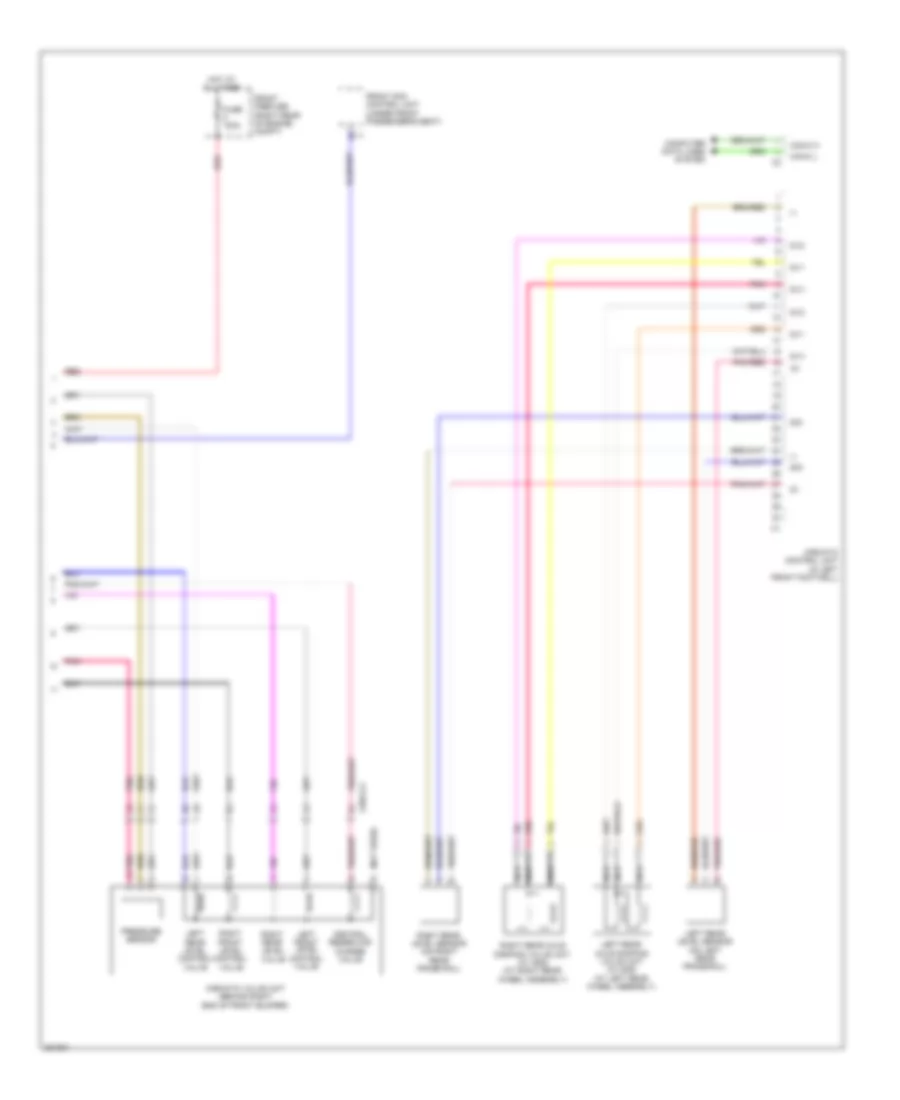
List of elements for Electronic Suspension Wiring Diagram (1 of 2) for Mercedes-Benz GL350 2012:
- (-)
- (top of left front shock tower) (w/ ads) left front body lateral acceleration sensor
- (top of right front shock tower) (w/ ads) right front body lateral acceleration sensor
- 87a
- Ablv
- Air suspension compressor relay
- Airmatic compressor unit (behind right side of front bumper)
- Airmatic control unit (in left front footwell)
- Circuit 31 left footwell voltage distributor connector 1
- Dv1
- Dv2
- Dvv
- Engine compartment fuse & relay box (right side of engine compt)
- Fuse 15a
- Fuse 40a
- Fuse 5a
- Hot at all times
- Hot in on or start
- Left front axle damping valve unit (w/ ads) (on left front axle)
- Left front level sensor (on left front frame rails)
- Load compartment fuse & relay box (right side of of cargo area)
- Mr1
- Mr2
- Nca
- Pnk
- Red
- Rel
- Right front axle damping valve unit (w/ ads) (on right front axle)
- Right front level sensor (on right front frame rails)
- Sig
- W15/2 (left front footwell)
- W2 (right side of engine compt)
- X25/2-c1
- X25/2-c2
- Zlv
Electronic Suspension Wiring Diagram (2 of 2) for Mercedes-Benz GL350 2012
List of elements for Electronic Suspension Wiring Diagram (2 of 2) for Mercedes-Benz GL350 2012:
- (-)
- (not used)
- Airmatic control unit (in left front footwell)
- Airmatic valve unit (behind right end of front bumper)
- Can-c h
- Can-c l
- Central reservoir charge valve
- Computer data lines system
- Dv1
- Dv2
- Dvv
- Front prefuse (right rear of engine compt)
- Front sam control unit (under front passenger's seat)
- Fuse 100a
- Hot at all times
- Left front level control valve
- Left rear axle damping valve unit (w/ ads) (at left rear wheel assembly)
- Left rear level control valve
- Left rear level sensor (on left rear frame rail)
- Nca
- Pnk
- Pnk/red
- Pressure sensor
- Red
- Right front level control valve
- Right rear axle damping valve unit (w/ ads) (at right rear wheel assembly)
- Right rear level sensor (on right rear frame rail)
- Right rear level valve
- Sig
- X25/2-c2