ELECTRONIC SUSPENSION
Electronic Suspension Wiring Diagram for Nissan Armada SL 2012
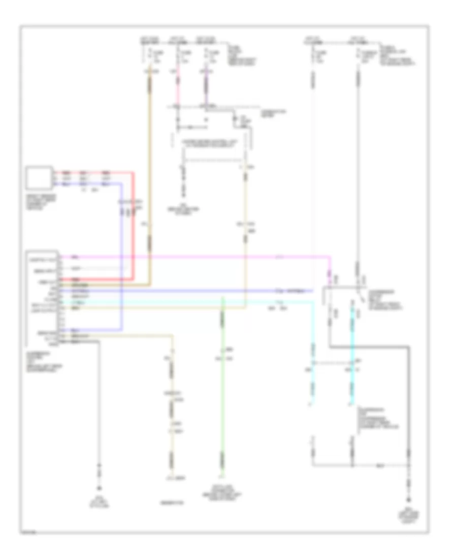
List of elements for Electronic Suspension Wiring Diagram for Nissan Armada SL 2012:
- 13p
- 25c
- 27c
- 28c
- 29c
- 34g m31
- 48c c1
- 62j
- 63j
- 64j m40
- 67j
- Alt in
- B19 (at left "d" pillar)
- B40
- B40 red
- B69
- Bat
- Ck susp ind
- Combination meter
- Comp rly out
- Compressor motor relay (at right front of engine compt)
- Data link connector (behind lower left side of dash)
- E130
- E131
- E152
- E201
- E205
- E24 (left side of engine compt)
- E34
- E40
- E41
- Exh vlv out
- Fuse & fusible link box (at right rear of engine compt)
- Fuse 10a
- Fuse block (j/b) (behind right end of dash)
- Fusible link g 30a
- Generator
- Gnd
- Height sensor (at right rear corner of vehicle)
- Hot at all times
- Hot in on or start
- Ign
- K-line
- Lamp output
- M24
- M39
- M40
- M61 (behind center of dash)
- Pnk
- Red
- Sens gnd
- Sens input
- Suspension air compressor (at right rear corner of vehicle)
- Suspension control unit (behind left rear quarterpanel)
- Unified meter control unit (w/ information display)
- Vref out
For engine performance wiring diagrams, see ENGINE PERFORMANCE WIRING DIAGRAMS article.
For additional transmission wiring diagrams, see TRANSMISSION WIRING DIAGRAMS article.
 English