ELECTRONIC SUSPENSION
Electronic Suspension Wiring Diagram for Toyota 4Runner SR5 2012
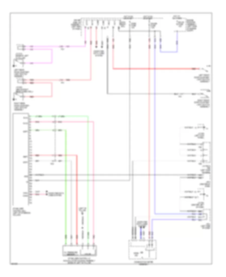
List of elements for Electronic Suspension Wiring Diagram for Toyota 4Runner SR5 2012:
- (left "b" pillar) o1
- A33
- A66
- A68
- Accumulator housing assembly (base of left "b" pillar)
- B14
- B15
- B20
- B22
- B63
- Becu
- C55
- Canh
- Canl
- Combination meter assembly
- Computer data lines system
- D39
- Driver side j/b assembly (left end of dash)
- Ecu-b fuse 10a
- Engine room r/b assembly (left side of engine compt)
- F27
- F55
- F56
- Flcy
- Fn1
- Fo1
- Fo2
- Frcy
- Gauge fuse 7.5a
- Gnd
- Hot at all times
- Hot in on or start
- J/b 4 (left side of dash)
- J/b 5 (center of dash)
- J/c f55 & f56 (left side of dash)
- J/c f63 (left kick panel)
- J/c f64 (center left of dash)
- J/c n22 (above right rear wheelwell)
- J/c o18 (base of left "c" pillar)
- Kdss fuse 10a
- Kdss ind
- Lcty
- Left front door courtesy light switch assembly
- Left rear door courtesy light switch assembly
- Main body ecu
- Oil pressure sensor
- Pnk
- Rcty
- Red
- Right front door courtesy light switch assembly
- Right rear door courtesy light switch assembly
- Sbp1
- Sgp1
- Slal
- Slau
- Sop1
- Stabilizer control ecu (left of steering column)
- Stabilizer control w/
- Valve
 English