ELECTRONIC SUSPENSION
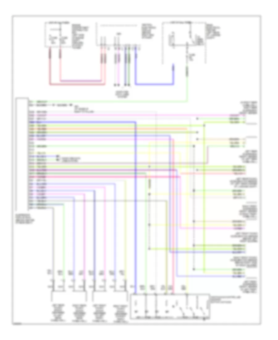
Electronic Suspension Wiring Diagram for Volvo S80 2007
List of elements for Electronic Suspension Wiring Diagram for Volvo S80 2007:
- (in right rear wheelwell) right rear suspension height sensor
- 15- feed rear relay
- C10
- C11
- C12
- C13
- C14
- C15
- C16
- C17
- C18
- C19
- C20
- C21
- C22
- C23
- C24
- C25
- C26
- C27
- C28
- C29
- Cem
- Central electronic module (behind right end of dash)
- Computer data lines system
- Continuous controlled damping switch unit(ccd)
- Engine compartment distribution box (left side of engine compt, forward of strut tower)
- Fuse a1 60a
- Fuse a2 60a
- Fuse b2 10a
- G67 (at base of right "c" pillar)
- Hot at all times
- Left front four-c acceleration sensor (behind left front bumper)
- Left front four-c shock absorber (in left front wheelwell)
- Left front suspension height sensor (in left front wheelwell)
- Left rear four-c acceleration sensor (at left rear corner of luggage compt)
- Left rear four-c shock absorber (in left rear wheelwell)
- Left rear suspension height sensor (in left rear wheelwell)
- Nca
- Rear electrical center (left rear of luggage compt)
- Right front four-c acceleration sensor (behind right side of front bumper)
- Right front four-c shock absorber (in right front wheelwell)
- Right front suspension height sensor (in right front wheelwell)
- Right rear four-c shock absorber (in right rear wheelwell)
- Suspension module (sum) (behind center of rear seat)
 English