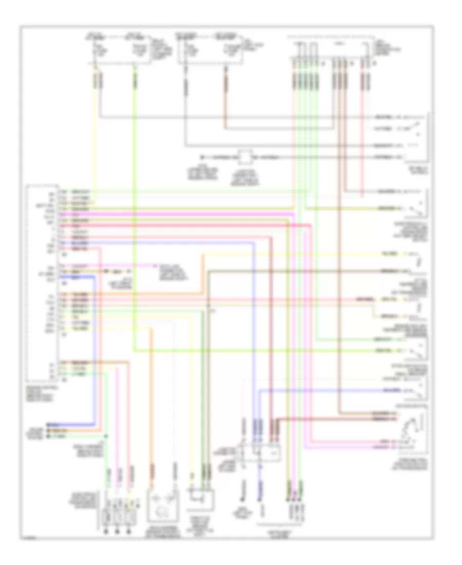
Автомтическая коробка Передач (АКПП) Полная привод (4WD) Блокировка Дифференциала
2.4L
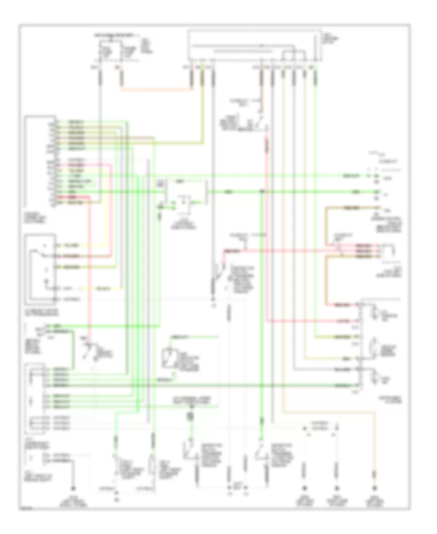
2.4L, схема перегрузки для Toyota Tacoma SR5 1997
2.4L, схема перегрузки для Toyota Tacoma SR5 1997 - Список элементов:
- (w/ tach)
- (w/o tach)
- A5 d1
- C12
- C13
- Canada
- Cig fuse 15a
- Combination meter
- Cruise control ecu (on right kick panel)
- D13
- D15
- D16
- D17
- D18
- D19
- Diode (behind top center of dash)
- Diode (behind top right side of dash)
- F19
- F20
- G201 (right side of dash)
- Guage fuse 10a
- Hot in accy or on
- Hot in on or start
- J/b 1 (behind dash, left side of steering column)
- J/b 3 (behind dash, above steering column)
- Junction connector 2 (behind left side of dash)
- Junction connector 4 (behind left side of dash)
- Junction connector 6 (above glove box) (w/ cruise control only)
- O/d cut relay (on right side of engine compt) (w/ cruise control)
- O/d main switch
- O/d off
- O/d solenoid (on transmission)
- Park/ neutral position switch (on transmission)
- Pnk
- Usa
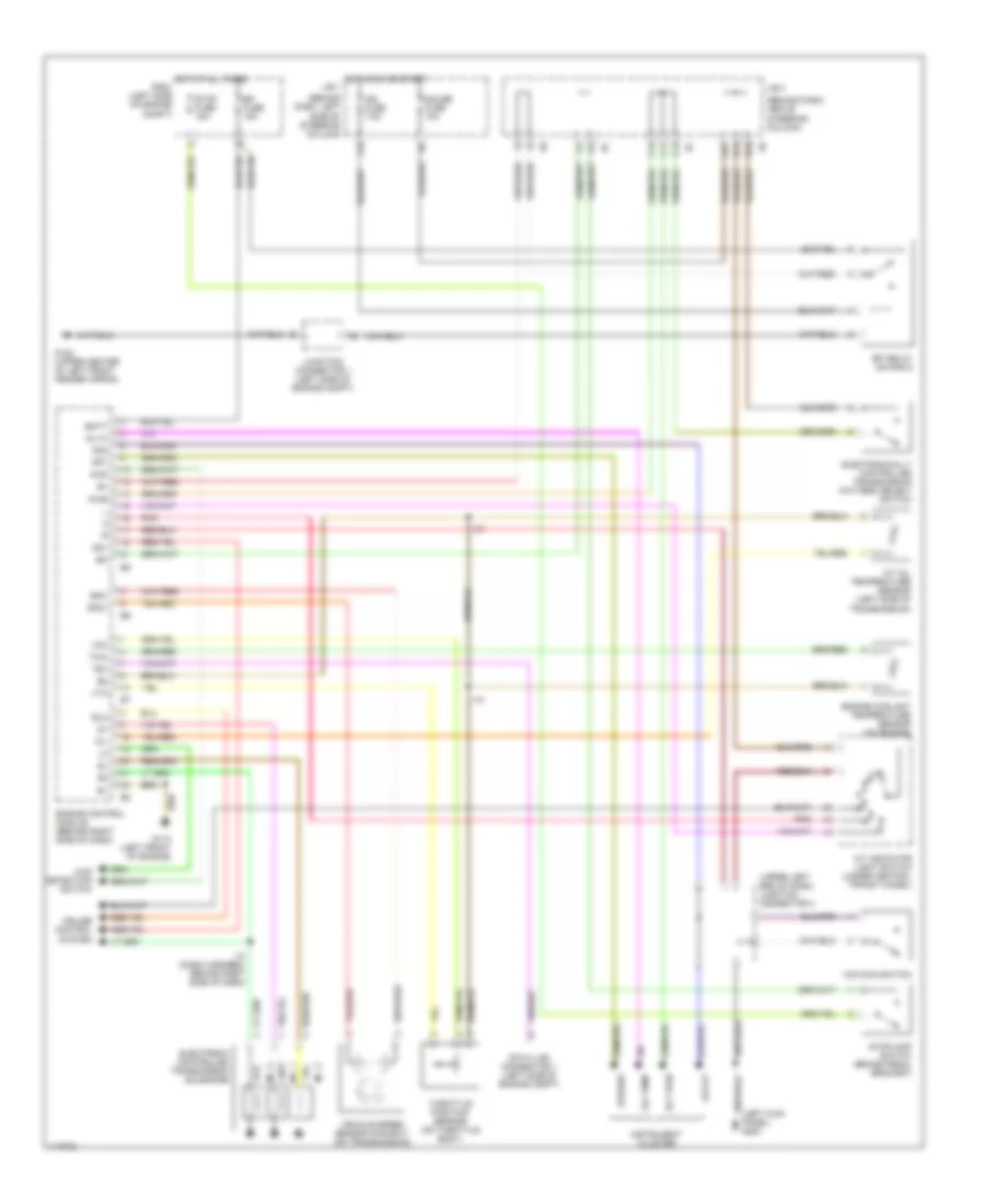
Электросхема Полного привода 4WD, С Избранный Переключатель 2-4 для Toyota Tacoma SR5 1997
Электросхема Полного привода 4WD, С Избранный Переключатель 2-4 для Toyota Tacoma SR5 1997 - Список элементов:
- (i/p harness, upper right side of dash) i10
- 2-4
- 2-4 select motor (on transmission)
- 2-4 select switch
- 4wd
- 4wd ecu (upper left kick panel)
- 4wd fuse 15a
- 4wd ind
- A/t ind switch
- A/t parking ind
- A10
- Abs ecu (below center of dash)
- Add indicator switch (left side of engine)
- B12
- C10
- C12
- C13
- D10
- D12
- D14
- D17
- D19
- Detection switch (transfer l4 position) (on trans- mission)
- Detection switch (transfer neutral position) (on trans- mission)
- Detection switch (transfer position) (on trans- mission)
- Engine control module (behind right side of dash)
- Exi
- Exi3
- F18
- F20
- Floor a/t
- Floor a/t only
- G102 (left front shock tower)
- G201 (right side of dash)
- G202 (left end of dash)
- Gauge fuse 10a
- Gnd
- Hot in run or start
- I10
- Ind
- Instrument cluster
- J/b 1 (left kick panel)
- J/b 3 (center of i/p)
- J/c 1 (left front of engine compt)
- J/c 4 (top left side of dash)
- J/c 6 (top right side of dash)
- J/c 7 (upper right side of dash)
- M/t
- Park/ neutral position switch
- Red
- Rl1
- Rl2
- Spd
- Tfn
- Th+
- Th-
- Vehicle speed sensor
- Vsv 2 (add) (left front of engine compt)
- Vsv 4 (add) (left front of engine compt)
- W/ abs
- W/o abs
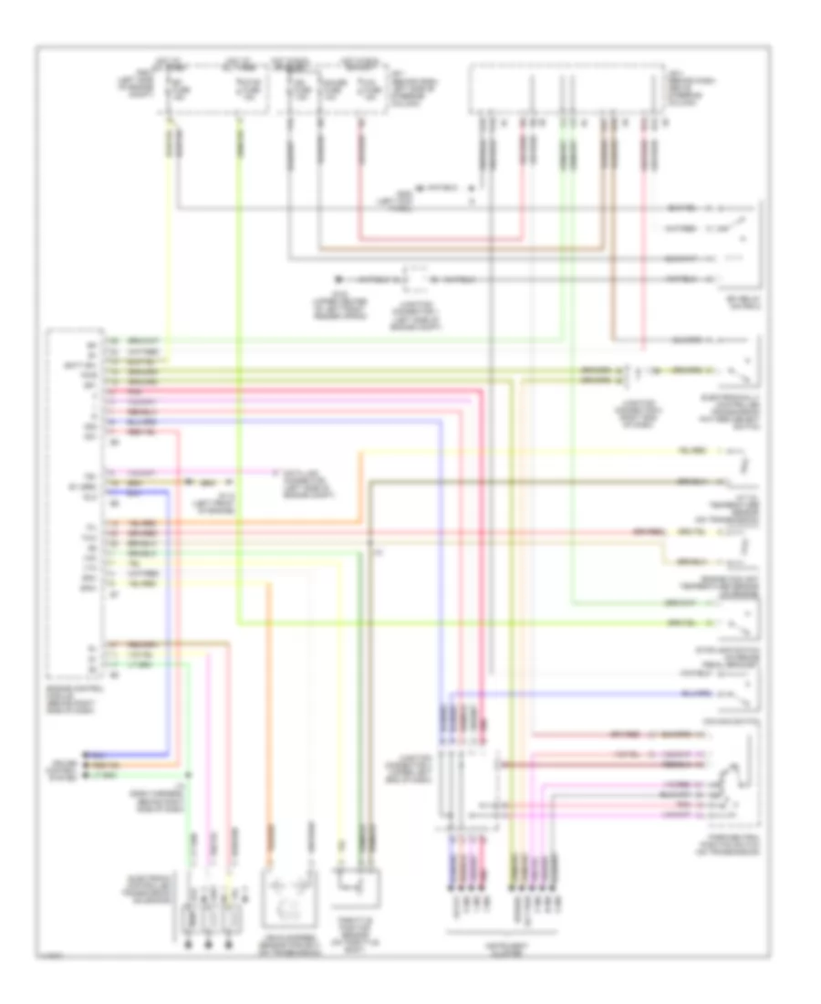
Электросхема Полного привода 4WD, без Избранный Переключатель 2-4 для Toyota Tacoma SR5 1997
Электросхема Полного привода 4WD, без Избранный Переключатель 2-4 для Toyota Tacoma SR5 1997 - Список элементов:
- (on trans- mission)
- 2.7l
- 3.4l a/t
- 3.4l m/t
- 4wd
- 4wd control ecu (w/ rear diff lock) (upper left kick panel)
- 4wd fuse 15a
- 4wd ind
- :floor a/t only
- :w/ abs
- :w/ add control relay
- :w/ rear diff lock
- :w/o abs
- :w/o add control relay
- :w/o rear diff lock
- A/t parking ind
- A10
- Abs ecu (below
- Abs ecu (below center of dash)
- Add control relay (upper right kick panel)
- Add indicator switch (left side of engine)
- B12
- C10
- C13
- Center of dash)
- D14
- D17
- D19
- Detection switch (transfer l4 position) (on trans- mission)
- Detection switch (transfer neutral position)
- Detection switch (transfer position) (on trans- mission)
- Engine control module (behind right side of dash)
- Exi
- Exi3
- F18
- F20
- From instrument cluster (diagram 1 of 1)
- G102 (left front shock tower)
- G201 (right side of dash)
- Gauge fuse 10a
- Hot in on or start
- I10
- I10 (i/p harn, upper right side
- Instrument cluster
- J/b 1 (left kick panel)
- J/b 3 (center of i/p)
- J/c 1 (left front of engine compt)
- J/c 6 (top right side of dash)
- J/c 7 (upper right side of dash)
- Of dash)
- Park/neutral position switch (a/t indicator switch) (transmission)
- Tfn
- To add indicator switch (diagram 1 of 1)
- Vsv 2 (add) (left front of engine compt)
- Vsv 4 (add) (left front of engine compt)
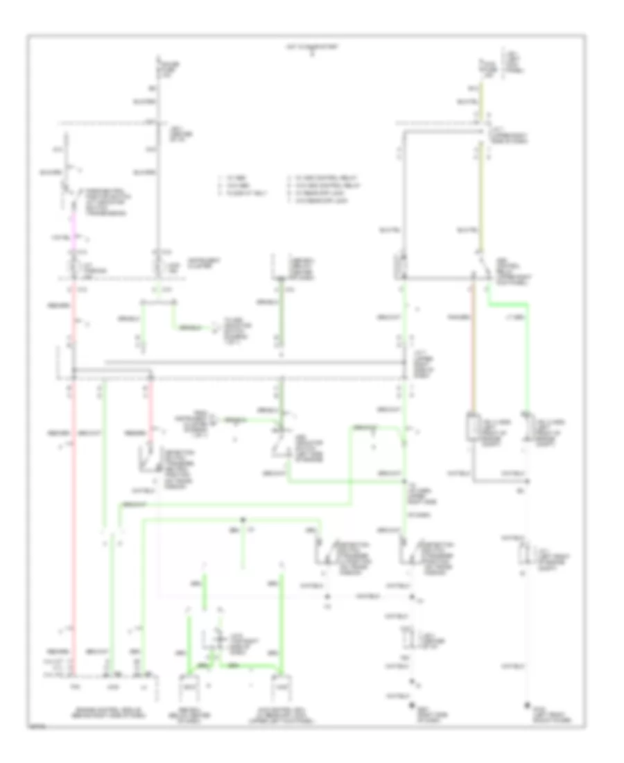
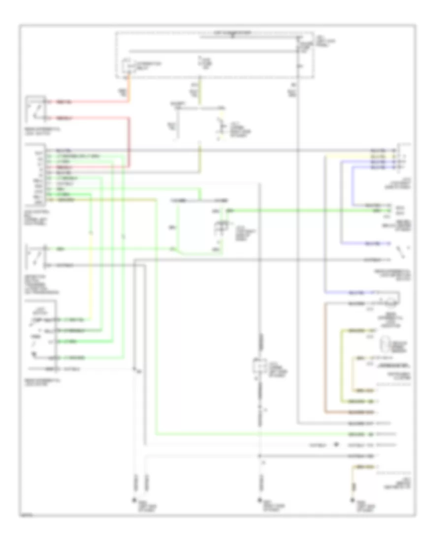
Электросхема блокировки заднего дифференциала для Toyota Tacoma SR5 1997
Электросхема блокировки заднего дифференциала для Toyota Tacoma SR5 1997 - Список элементов:
- (speedometer)
- 3.4l
- 4wd
- 4wd control ecu (upper left kick panel)
- 4wd fuse 15a
- A10
- Abs ecu (below center of dash)
- B12
- C10
- C12
- C13
- D10
- D12
- D15
- D17
- Detection switch (transfer l4 position) (on transmission)
- Except 3.4l
- Exi2
- Exi3
- F18
- F20
- Free
- G201 (right side of dash)
- G202 (left end of dash)
- Gauge fuse 10a
- Gnd
- Hot in on or start
- I10
- Instrument cluster
- Integration relay
- J/b 1 (left kick panel)
- J/b 3 (behind center of i/p)
- J/c 2 (upper left side of dash)
- J/c 5 (top right side of dash)
- J/c 6 (top right side of dash)
- J/c 7 (upper right side of dash)
- Limit switch
- Lock
- Rear differential lock switch
- Rear differential lock detection switch
- Rear differential lock indicator
- Rear differential lock motor
- Rel1
- Rel2
- Rlp
- Spd
- Vehicle speed sensor
- W/ abs
- W/o abs
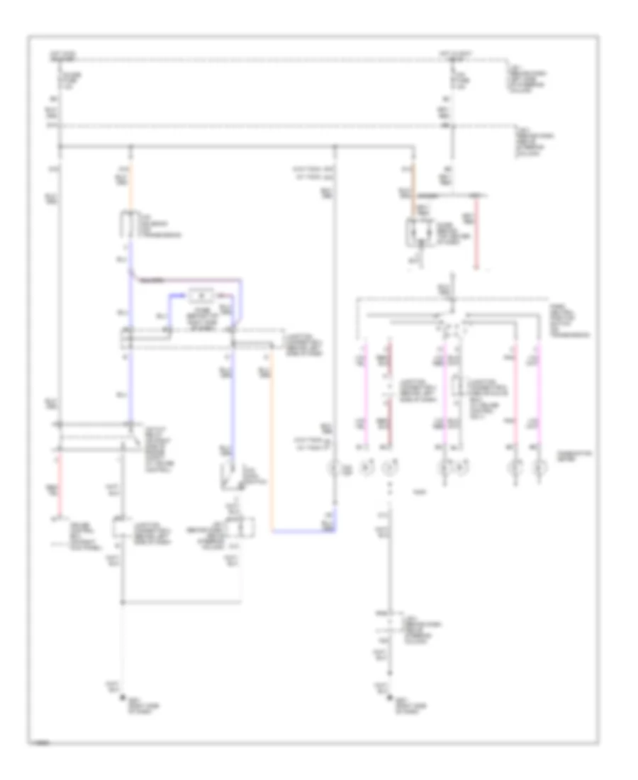
Электросхема раздатки, С Избранный Переключатель 2-4 для Toyota Tacoma SR5 1997
Электросхема раздатки, С Избранный Переключатель 2-4 для Toyota Tacoma SR5 1997 - Список элементов:
- (i/p harness, upper right side of dash) i10
- 2-4
- 2-4 select motor (on transmission)
- 2-4 select switch
- 4wd
- 4wd ecu (upper left kick panel)
- 4wd fuse 15a
- 4wd ind
- A/t ind switch
- A/t parking ind
- A10
- Abs ecu (below center of dash)
- Add indicator switch (left side of engine)
- B12
- C10
- C12
- C13
- D10
- D12
- D14
- D17
- D19
- Detection switch (transfer l4 position) (on trans- mission)
- Detection switch (transfer neutral position) (on trans- mission)
- Detection switch (transfer position) (on trans- mission)
- Engine control module (behind right side of dash)
- Exi
- Exi3
- F18
- F20
- Floor a/t
- Floor a/t only
- G102 (left front shock tower)
- G201 (right side of dash)
- G202 (left end of dash)
- Gauge fuse 10a
- Gnd
- Hot in run or start
- I10
- Ind
- Instrument cluster
- J/b 1 (left kick panel)
- J/b 3 (center of i/p)
- J/c 1 (left front of engine compt)
- J/c 4 (top left side of dash)
- J/c 6 (top right side of dash)
- J/c 7 (upper right side of dash)
- M/t
- Park/ neutral position switch
- Red
- Rl1
- Rl2
- Spd
- Tfn
- Th+
- Th-
- Vehicle speed sensor
- Vsv 2 (add) (left front of engine compt)
- Vsv 4 (add) (left front of engine compt)
- W/ abs
- W/o abs
Электросхема раздатки, без Избранный Переключатель 2-4 для Toyota Tacoma SR5 1997
Электросхема раздатки, без Избранный Переключатель 2-4 для Toyota Tacoma SR5 1997 - Список элементов:
- (on trans- mission)
- 2.7l
- 3.4l a/t
- 3.4l m/t
- 4wd
- 4wd control ecu (w/ rear diff lock) (upper left kick panel)
- 4wd fuse 15a
- 4wd ind
- :floor a/t only
- :w/ abs
- :w/ add control relay
- :w/ rear diff lock
- :w/o abs
- :w/o add control relay
- :w/o rear diff lock
- A/t parking ind
- A10
- Abs ecu (below
- Abs ecu (below center of dash)
- Add control relay (upper right kick panel)
- Add indicator switch (left side of engine)
- B12
- C10
- C13
- Center of dash)
- D14
- D17
- D19
- Detection switch (transfer l4 position) (on trans- mission)
- Detection switch (transfer neutral position)
- Detection switch (transfer position) (on trans- mission)
- Engine control module (behind right side of dash)
- Exi
- Exi3
- F18
- F20
- From instrument cluster (diagram 1 of 1)
- G102 (left front shock tower)
- G201 (right side of dash)
- Gauge fuse 10a
- Hot in on or start
- I10
- I10 (i/p harn, upper right side
- Instrument cluster
- J/b 1 (left kick panel)
- J/b 3 (center of i/p)
- J/c 1 (left front of engine compt)
- J/c 6 (top right side of dash)
- J/c 7 (upper right side of dash)
- Of dash)
- Park/neutral position switch (a/t indicator switch) (transmission)
- Tfn
- To add indicator switch (diagram 1 of 1)
- Vsv 2 (add) (left front of engine compt)
- Vsv 4 (add) (left front of engine compt)
2.7L
2.7L, Электросхема автоматической коробки передач АКПП для Toyota Tacoma SR5 1997
2.7L, Электросхема автоматической коробки передач АКПП для Toyota Tacoma SR5 1997 - Список элементов:
- (behind dash, above steering column)
- (behind dash, left
- (left kick panel) g200
- (upper left end of dash) junction connector 4
- 4wd
- 4wd detection switch
- A/t indicator light switch (under central trans tunnel)
- A/t oil temperature sensor (left side of transmission)
- Batt
- C11
- C12
- C13
- Cruise control system
- D14
- D16
- D17
- Data link connector 1 (left side of engine compt)
- Ect pwr
- Efi fuse 15a
- Efi relay (on r/b 2)
- Electronic controlled transmission solenoids
- Electronically controlled transmission pattern select switch
- Engine control module (behind right side of dash)
- Engine coolant temperature sensor (on engine)
- F15
- G102 (upper center of left front fender apron)
- G110 (left front of engine)
- Gauge fuse 10a
- Hot at all times r/b 2 (left side of engine compt)
- Hot in on or start j/b 1
- I10
- I10 (dash harness, behind right side of dash)
- Idl0
- Ign fuse 7.5a
- Instrument cluster
- J/b 3
- Junction connector 1 (left side of engine compt)
- No. 1
- No. 2
- No. 3
- O/d main switch
- Od off
- Od1
- Od2
- Oil
- Oil temp
- Oil-w
- Pnk
- Pwr
- Side of steering column)
- Sp1
- Sp2+
- Sp2-
- Speedo
- Stop fuse 15a
- Stoplamp switch (brake pedal bracket)
- Te1
- Throttle position sensor (on throttle body)
- Thw
- Vcc
- Vehicle speed sensor (for ect) (on transmission)
- Vta
Электросхема Полного привода 4WD, С Избранный Переключатель 2-4 для Toyota Tacoma SR5 1997
Электросхема Полного привода 4WD, С Избранный Переключатель 2-4 для Toyota Tacoma SR5 1997 - Список элементов:
- (i/p harness, upper right side of dash) i10
- 2-4
- 2-4 select motor (on transmission)
- 2-4 select switch
- 4wd
- 4wd ecu (upper left kick panel)
- 4wd fuse 15a
- 4wd ind
- A/t ind switch
- A/t parking ind
- A10
- Abs ecu (below center of dash)
- Add indicator switch (left side of engine)
- B12
- C10
- C12
- C13
- D10
- D12
- D14
- D17
- D19
- Detection switch (transfer l4 position) (on trans- mission)
- Detection switch (transfer neutral position) (on trans- mission)
- Detection switch (transfer position) (on trans- mission)
- Engine control module (behind right side of dash)
- Exi
- Exi3
- F18
- F20
- Floor a/t
- Floor a/t only
- G102 (left front shock tower)
- G201 (right side of dash)
- G202 (left end of dash)
- Gauge fuse 10a
- Gnd
- Hot in run or start
- I10
- Ind
- Instrument cluster
- J/b 1 (left kick panel)
- J/b 3 (center of i/p)
- J/c 1 (left front of engine compt)
- J/c 4 (top left side of dash)
- J/c 6 (top right side of dash)
- J/c 7 (upper right side of dash)
- M/t
- Park/ neutral position switch
- Red
- Rl1
- Rl2
- Spd
- Tfn
- Th+
- Th-
- Vehicle speed sensor
- Vsv 2 (add) (left front of engine compt)
- Vsv 4 (add) (left front of engine compt)
- W/ abs
- W/o abs
Электросхема Полного привода 4WD, без Избранный Переключатель 2-4 для Toyota Tacoma SR5 1997
Электросхема Полного привода 4WD, без Избранный Переключатель 2-4 для Toyota Tacoma SR5 1997 - Список элементов:
- (on trans- mission)
- 2.7l
- 3.4l a/t
- 3.4l m/t
- 4wd
- 4wd control ecu (w/ rear diff lock) (upper left kick panel)
- 4wd fuse 15a
- 4wd ind
- :floor a/t only
- :w/ abs
- :w/ add control relay
- :w/ rear diff lock
- :w/o abs
- :w/o add control relay
- :w/o rear diff lock
- A/t parking ind
- A10
- Abs ecu (below
- Abs ecu (below center of dash)
- Add control relay (upper right kick panel)
- Add indicator switch (left side of engine)
- B12
- C10
- C13
- Center of dash)
- D14
- D17
- D19
- Detection switch (transfer l4 position) (on trans- mission)
- Detection switch (transfer neutral position)
- Detection switch (transfer position) (on trans- mission)
- Engine control module (behind right side of dash)
- Exi
- Exi3
- F18
- F20
- From instrument cluster (diagram 1 of 1)
- G102 (left front shock tower)
- G201 (right side of dash)
- Gauge fuse 10a
- Hot in on or start
- I10
- I10 (i/p harn, upper right side
- Instrument cluster
- J/b 1 (left kick panel)
- J/b 3 (center of i/p)
- J/c 1 (left front of engine compt)
- J/c 6 (top right side of dash)
- J/c 7 (upper right side of dash)
- Of dash)
- Park/neutral position switch (a/t indicator switch) (transmission)
- Tfn
- To add indicator switch (diagram 1 of 1)
- Vsv 2 (add) (left front of engine compt)
- Vsv 4 (add) (left front of engine compt)
Электросхема блокировки заднего дифференциала для Toyota Tacoma SR5 1997
Электросхема блокировки заднего дифференциала для Toyota Tacoma SR5 1997 - Список элементов:
- (speedometer)
- 3.4l
- 4wd
- 4wd control ecu (upper left kick panel)
- 4wd fuse 15a
- A10
- Abs ecu (below center of dash)
- B12
- C10
- C12
- C13
- D10
- D12
- D15
- D17
- Detection switch (transfer l4 position) (on transmission)
- Except 3.4l
- Exi2
- Exi3
- F18
- F20
- Free
- G201 (right side of dash)
- G202 (left end of dash)
- Gauge fuse 10a
- Gnd
- Hot in on or start
- I10
- Instrument cluster
- Integration relay
- J/b 1 (left kick panel)
- J/b 3 (behind center of i/p)
- J/c 2 (upper left side of dash)
- J/c 5 (top right side of dash)
- J/c 6 (top right side of dash)
- J/c 7 (upper right side of dash)
- Limit switch
- Lock
- Rear differential lock switch
- Rear differential lock detection switch
- Rear differential lock indicator
- Rear differential lock motor
- Rel1
- Rel2
- Rlp
- Spd
- Vehicle speed sensor
- W/ abs
- W/o abs
Электросхема раздатки, С Избранный Переключатель 2-4 для Toyota Tacoma SR5 1997
Электросхема раздатки, С Избранный Переключатель 2-4 для Toyota Tacoma SR5 1997 - Список элементов:
- (i/p harness, upper right side of dash) i10
- 2-4
- 2-4 select motor (on transmission)
- 2-4 select switch
- 4wd
- 4wd ecu (upper left kick panel)
- 4wd fuse 15a
- 4wd ind
- A/t ind switch
- A/t parking ind
- A10
- Abs ecu (below center of dash)
- Add indicator switch (left side of engine)
- B12
- C10
- C12
- C13
- D10
- D12
- D14
- D17
- D19
- Detection switch (transfer l4 position) (on trans- mission)
- Detection switch (transfer neutral position) (on trans- mission)
- Detection switch (transfer position) (on trans- mission)
- Engine control module (behind right side of dash)
- Exi
- Exi3
- F18
- F20
- Floor a/t
- Floor a/t only
- G102 (left front shock tower)
- G201 (right side of dash)
- G202 (left end of dash)
- Gauge fuse 10a
- Gnd
- Hot in run or start
- I10
- Ind
- Instrument cluster
- J/b 1 (left kick panel)
- J/b 3 (center of i/p)
- J/c 1 (left front of engine compt)
- J/c 4 (top left side of dash)
- J/c 6 (top right side of dash)
- J/c 7 (upper right side of dash)
- M/t
- Park/ neutral position switch
- Red
- Rl1
- Rl2
- Spd
- Tfn
- Th+
- Th-
- Vehicle speed sensor
- Vsv 2 (add) (left front of engine compt)
- Vsv 4 (add) (left front of engine compt)
- W/ abs
- W/o abs
Электросхема раздатки, без Избранный Переключатель 2-4 для Toyota Tacoma SR5 1997
Электросхема раздатки, без Избранный Переключатель 2-4 для Toyota Tacoma SR5 1997 - Список элементов:
- (on trans- mission)
- 2.7l
- 3.4l a/t
- 3.4l m/t
- 4wd
- 4wd control ecu (w/ rear diff lock) (upper left kick panel)
- 4wd fuse 15a
- 4wd ind
- :floor a/t only
- :w/ abs
- :w/ add control relay
- :w/ rear diff lock
- :w/o abs
- :w/o add control relay
- :w/o rear diff lock
- A/t parking ind
- A10
- Abs ecu (below
- Abs ecu (below center of dash)
- Add control relay (upper right kick panel)
- Add indicator switch (left side of engine)
- B12
- C10
- C13
- Center of dash)
- D14
- D17
- D19
- Detection switch (transfer l4 position) (on trans- mission)
- Detection switch (transfer neutral position)
- Detection switch (transfer position) (on trans- mission)
- Engine control module (behind right side of dash)
- Exi
- Exi3
- F18
- F20
- From instrument cluster (diagram 1 of 1)
- G102 (left front shock tower)
- G201 (right side of dash)
- Gauge fuse 10a
- Hot in on or start
- I10
- I10 (i/p harn, upper right side
- Instrument cluster
- J/b 1 (left kick panel)
- J/b 3 (center of i/p)
- J/c 1 (left front of engine compt)
- J/c 6 (top right side of dash)
- J/c 7 (upper right side of dash)
- Of dash)
- Park/neutral position switch (a/t indicator switch) (transmission)
- Tfn
- To add indicator switch (diagram 1 of 1)
- Vsv 2 (add) (left front of engine compt)
- Vsv 4 (add) (left front of engine compt)
3.4L
3.4L, Электросхема автоматической коробки передач АКПП, С Изменение Колонки для Toyota Tacoma SR5 1997
3.4L, Электросхема автоматической коробки передач АКПП, С Изменение Колонки для Toyota Tacoma SR5 1997 - Список элементов:
- 2 ind
- A/t oil temperature sensor (on transmission)
- Batt (b+)
- C12
- C13
- Cig fuse 15a
- Cruise control system
- D ind
- D16
- D17
- Data link connector (left side of engine compt)
- E1 (grd)
- E12
- E13
- Ect pwr
- Efi fuse 15a
- Efi relay (on r/b 2)
- Electronic controlled transmission solenoids
- Electronically controlled transmission pattern select switch
- Engine control module (behind right side of dash)
- Engine coolant temperature sensor (on engine)
- F15
- G102 (upper center of left front fender apron)
- G110 (left front of engine)
- G200 (left kick panel)
- Gauge fuse 10a
- Hot at all times
- Hot in run or accy
- Hot in run or start
- I10
- I10 (dash harness, behind right side of dash)
- Idl0
- Ign fuse 7.5a
- Instrument cluster
- J/b 1 (behind dash, left side of steering column)
- J/b 3 (behind dash, above steering column)
- Junction connector 1 (left side of engine compt)
- Junction connector 4 (upper left end of dash)
- Junction connector 8 (right end of dash)
- L ind
- N ind
- No. 1
- No. 2
- No. 3
- O/d main switch
- Od off
- Od1
- Od2
- Oil
- P ind
- Park/neutral position switch (on transmission)
- Pnk
- Pwr
- R ind
- R/b 2 (left side of engine compt)
- Sp1
- Sp2+
- Sp2-
- Speedo
- Stop fuse 15a
- Stoplamp switch (on brake pedal bracket)
- Te1
- Throttle position sensor (on throttle body)
- Thw
- Vcc
- Vehicle speed sensor (for ect) (on transmission)
- Vta
3.4L, Электросхема автоматической коробки передач АКПП, С Изменение Пола для Toyota Tacoma SR5 1997
3.4L, Электросхема автоматической коробки передач АКПП, С Изменение Пола для Toyota Tacoma SR5 1997 - Список элементов:
- A/t oil temperature sensor (on transmission)
- Batt (b+)
- C11
- C12
- C13
- Cruise control system
- D14
- D16
- D17
- Data link connector (left side of engine compt)
- E1 (grd)
- E12
- E13
- Ect pwr
- Efi fuse 15a
- Efi relay (on r/b 2)
- Electronic controlled transmission solenoids
- Electronically controlled transmission pattern select switch
- Engine control module (behind right side of dash)
- Engine coolant temperature sensor (on engine)
- F15
- G102 (upper center of left front fender apron)
- G110 (left front of engine)
- G200 (left kick panel)
- Gauge fuse 10a
- Hot at all times
- Hot in run or start
- I10
- I10 (dash harness, behind right side of dash)
- Idl0
- Ign fuse 7.5a
- Instrument cluster
- J/b 1 (left kick panel)
- J/b 3 (behind combination meter)
- Junction connector (upper left end of dash)
- Junction connector 1 (left side of engine compt)
- No. 1
- No. 2
- No. 3
- O/d main switch
- Od off
- Od1
- Od2
- Oil
- Oil temp
- Oil-w
- Park/neutral position switch (on transmission)
- Pnk
- Pwr
- Relay block 2 (left side of engine compt)
- Sp1
- Sp2+
- Sp2-
- Speedo
- Stop fuse 15a
- Stoplamp switch (on brake pedal bracket)
- Te1
- Throttle position sensor (on throttle body)
- Thw
- Vcc
- Vehicle speed sensor (for ect) (on transmission)
- Vta
Электросхема Полного привода 4WD, С Избранный Переключатель 2-4 для Toyota Tacoma SR5 1997
Электросхема Полного привода 4WD, С Избранный Переключатель 2-4 для Toyota Tacoma SR5 1997 - Список элементов:
- (i/p harness, upper right side of dash) i10
- 2-4
- 2-4 select motor (on transmission)
- 2-4 select switch
- 4wd
- 4wd ecu (upper left kick panel)
- 4wd fuse 15a
- 4wd ind
- A/t ind switch
- A/t parking ind
- A10
- Abs ecu (below center of dash)
- Add indicator switch (left side of engine)
- B12
- C10
- C12
- C13
- D10
- D12
- D14
- D17
- D19
- Detection switch (transfer l4 position) (on trans- mission)
- Detection switch (transfer neutral position) (on trans- mission)
- Detection switch (transfer position) (on trans- mission)
- Engine control module (behind right side of dash)
- Exi
- Exi3
- F18
- F20
- Floor a/t
- Floor a/t only
- G102 (left front shock tower)
- G201 (right side of dash)
- G202 (left end of dash)
- Gauge fuse 10a
- Gnd
- Hot in run or start
- I10
- Ind
- Instrument cluster
- J/b 1 (left kick panel)
- J/b 3 (center of i/p)
- J/c 1 (left front of engine compt)
- J/c 4 (top left side of dash)
- J/c 6 (top right side of dash)
- J/c 7 (upper right side of dash)
- M/t
- Park/ neutral position switch
- Red
- Rl1
- Rl2
- Spd
- Tfn
- Th+
- Th-
- Vehicle speed sensor
- Vsv 2 (add) (left front of engine compt)
- Vsv 4 (add) (left front of engine compt)
- W/ abs
- W/o abs
Электросхема Полного привода 4WD, без Избранный Переключатель 2-4 для Toyota Tacoma SR5 1997
Электросхема Полного привода 4WD, без Избранный Переключатель 2-4 для Toyota Tacoma SR5 1997 - Список элементов:
- (on trans- mission)
- 2.7l
- 3.4l a/t
- 3.4l m/t
- 4wd
- 4wd control ecu (w/ rear diff lock) (upper left kick panel)
- 4wd fuse 15a
- 4wd ind
- :floor a/t only
- :w/ abs
- :w/ add control relay
- :w/ rear diff lock
- :w/o abs
- :w/o add control relay
- :w/o rear diff lock
- A/t parking ind
- A10
- Abs ecu (below
- Abs ecu (below center of dash)
- Add control relay (upper right kick panel)
- Add indicator switch (left side of engine)
- B12
- C10
- C13
- Center of dash)
- D14
- D17
- D19
- Detection switch (transfer l4 position) (on trans- mission)
- Detection switch (transfer neutral position)
- Detection switch (transfer position) (on trans- mission)
- Engine control module (behind right side of dash)
- Exi
- Exi3
- F18
- F20
- From instrument cluster (diagram 1 of 1)
- G102 (left front shock tower)
- G201 (right side of dash)
- Gauge fuse 10a
- Hot in on or start
- I10
- I10 (i/p harn, upper right side
- Instrument cluster
- J/b 1 (left kick panel)
- J/b 3 (center of i/p)
- J/c 1 (left front of engine compt)
- J/c 6 (top right side of dash)
- J/c 7 (upper right side of dash)
- Of dash)
- Park/neutral position switch (a/t indicator switch) (transmission)
- Tfn
- To add indicator switch (diagram 1 of 1)
- Vsv 2 (add) (left front of engine compt)
- Vsv 4 (add) (left front of engine compt)
Электросхема блокировки заднего дифференциала для Toyota Tacoma SR5 1997
Электросхема блокировки заднего дифференциала для Toyota Tacoma SR5 1997 - Список элементов:
- (speedometer)
- 3.4l
- 4wd
- 4wd control ecu (upper left kick panel)
- 4wd fuse 15a
- A10
- Abs ecu (below center of dash)
- B12
- C10
- C12
- C13
- D10
- D12
- D15
- D17
- Detection switch (transfer l4 position) (on transmission)
- Except 3.4l
- Exi2
- Exi3
- F18
- F20
- Free
- G201 (right side of dash)
- G202 (left end of dash)
- Gauge fuse 10a
- Gnd
- Hot in on or start
- I10
- Instrument cluster
- Integration relay
- J/b 1 (left kick panel)
- J/b 3 (behind center of i/p)
- J/c 2 (upper left side of dash)
- J/c 5 (top right side of dash)
- J/c 6 (top right side of dash)
- J/c 7 (upper right side of dash)
- Limit switch
- Lock
- Rear differential lock switch
- Rear differential lock detection switch
- Rear differential lock indicator
- Rear differential lock motor
- Rel1
- Rel2
- Rlp
- Spd
- Vehicle speed sensor
- W/ abs
- W/o abs
Электросхема раздатки, С Избранный Переключатель 2-4 для Toyota Tacoma SR5 1997
Электросхема раздатки, С Избранный Переключатель 2-4 для Toyota Tacoma SR5 1997 - Список элементов:
- (i/p harness, upper right side of dash) i10
- 2-4
- 2-4 select motor (on transmission)
- 2-4 select switch
- 4wd
- 4wd ecu (upper left kick panel)
- 4wd fuse 15a
- 4wd ind
- A/t ind switch
- A/t parking ind
- A10
- Abs ecu (below center of dash)
- Add indicator switch (left side of engine)
- B12
- C10
- C12
- C13
- D10
- D12
- D14
- D17
- D19
- Detection switch (transfer l4 position) (on trans- mission)
- Detection switch (transfer neutral position) (on trans- mission)
- Detection switch (transfer position) (on trans- mission)
- Engine control module (behind right side of dash)
- Exi
- Exi3
- F18
- F20
- Floor a/t
- Floor a/t only
- G102 (left front shock tower)
- G201 (right side of dash)
- G202 (left end of dash)
- Gauge fuse 10a
- Gnd
- Hot in run or start
- I10
- Ind
- Instrument cluster
- J/b 1 (left kick panel)
- J/b 3 (center of i/p)
- J/c 1 (left front of engine compt)
- J/c 4 (top left side of dash)
- J/c 6 (top right side of dash)
- J/c 7 (upper right side of dash)
- M/t
- Park/ neutral position switch
- Red
- Rl1
- Rl2
- Spd
- Tfn
- Th+
- Th-
- Vehicle speed sensor
- Vsv 2 (add) (left front of engine compt)
- Vsv 4 (add) (left front of engine compt)
- W/ abs
- W/o abs
Электросхема раздатки, без Избранный Переключатель 2-4 для Toyota Tacoma SR5 1997
Электросхема раздатки, без Избранный Переключатель 2-4 для Toyota Tacoma SR5 1997 - Список элементов:
- (on trans- mission)
- 2.7l
- 3.4l a/t
- 3.4l m/t
- 4wd
- 4wd control ecu (w/ rear diff lock) (upper left kick panel)
- 4wd fuse 15a
- 4wd ind
- :floor a/t only
- :w/ abs
- :w/ add control relay
- :w/ rear diff lock
- :w/o abs
- :w/o add control relay
- :w/o rear diff lock
- A/t parking ind
- A10
- Abs ecu (below
- Abs ecu (below center of dash)
- Add control relay (upper right kick panel)
- Add indicator switch (left side of engine)
- B12
- C10
- C13
- Center of dash)
- D14
- D17
- D19
- Detection switch (transfer l4 position) (on trans- mission)
- Detection switch (transfer neutral position)
- Detection switch (transfer position) (on trans- mission)
- Engine control module (behind right side of dash)
- Exi
- Exi3
- F18
- F20
- From instrument cluster (diagram 1 of 1)
- G102 (left front shock tower)
- G201 (right side of dash)
- Gauge fuse 10a
- Hot in on or start
- I10
- I10 (i/p harn, upper right side
- Instrument cluster
- J/b 1 (left kick panel)
- J/b 3 (center of i/p)
- J/c 1 (left front of engine compt)
- J/c 6 (top right side of dash)
- J/c 7 (upper right side of dash)
- Of dash)
- Park/neutral position switch (a/t indicator switch) (transmission)
- Tfn
- To add indicator switch (diagram 1 of 1)
- Vsv 2 (add) (left front of engine compt)
- Vsv 4 (add) (left front of engine compt)

 Čeština
 Dansk
Dansk Deutsch
 English
 English
 Español
 Suomi
Suomi Français
 Français
 עברית
עברית Hrvatski
 Magyar
 Italiano
 日本語
日本語 한국어
한국어 Nederlands
 Polski
 Português
 Português
 Română
 Русский
 Slovenčina
 Slovenščina
 Svenska
 Türkçe
 中文 (中国)

 Полная привод (4WD) Блокировка Дифференциала Toyota Tacoma SR5 1997")