БЛОК ПРЕДОХРАНИТЕЛЕЙ И РЕЛЕ
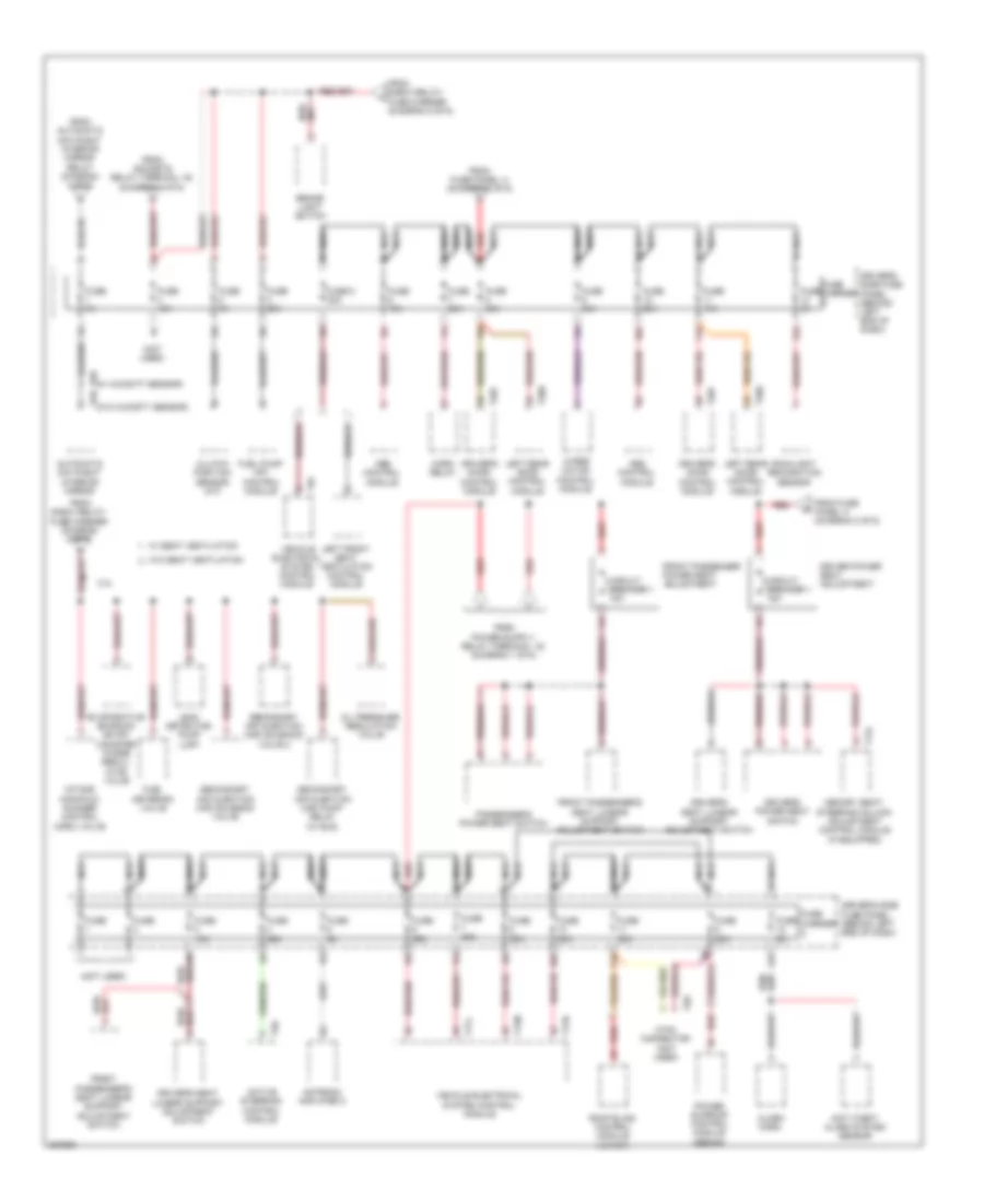
Электросхема блока предохранителей и реле (1 из 6) для Audi A4 2.0T Avant Quattro 2010

Электросхема блока предохранителей и реле (1 из 6) для Audi A4 2.0T Avant Quattro 2010 - Список элементов:
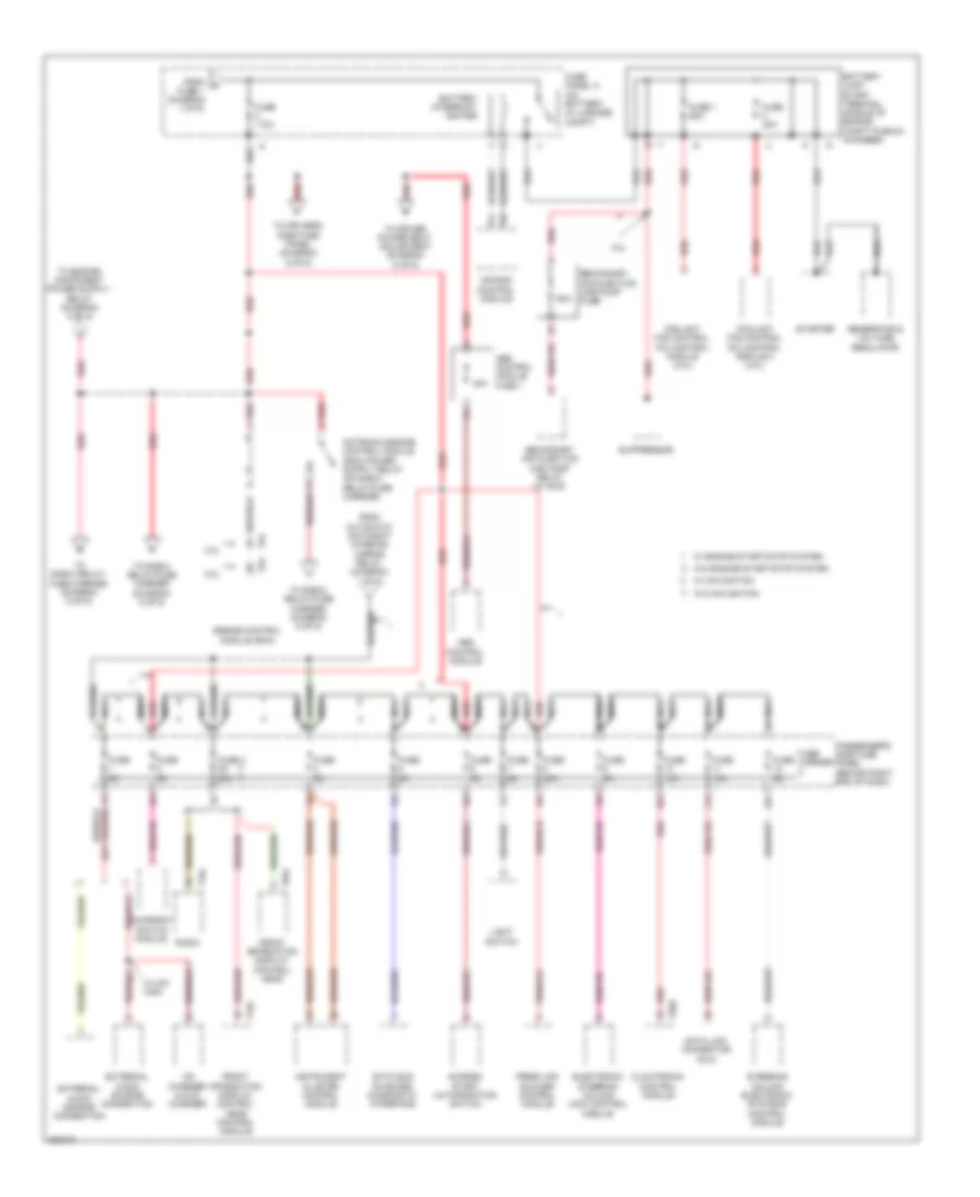
Электросхема блока предохранителей и реле (2 из 6) для Audi A4 2.0T Avant Quattro 2010
Электросхема блока предохранителей и реле (2 из 6) для Audi A4 2.0T Avant Quattro 2010 - Список элементов:
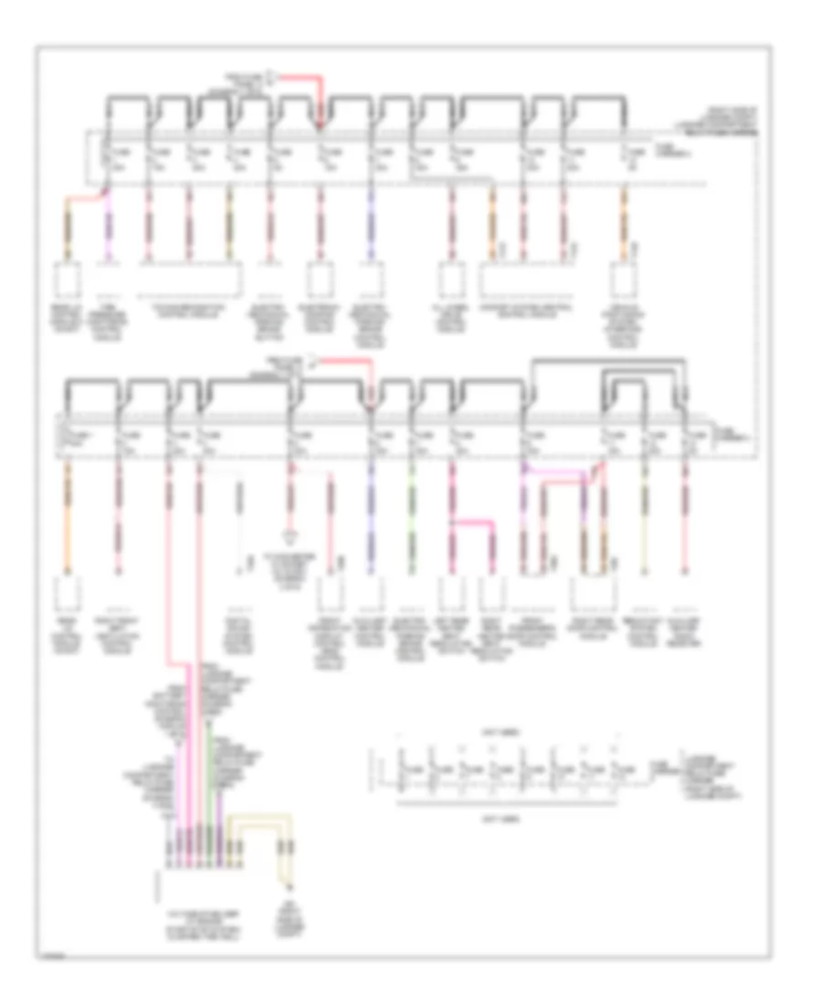
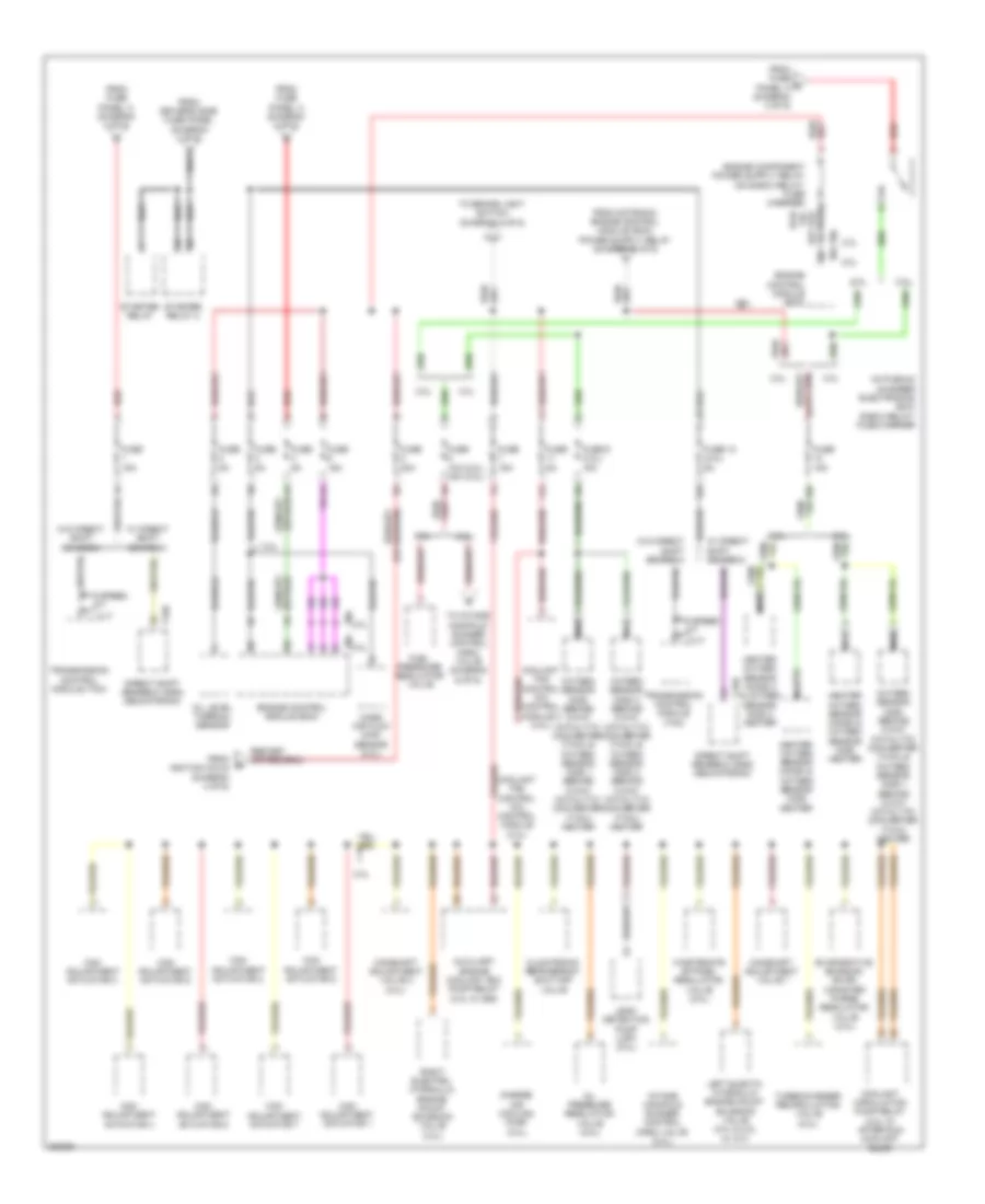
Электросхема блока предохранителей и реле (3 из 6) для Audi A4 2.0T Avant Quattro 2010
Электросхема блока предохранителей и реле (3 из 6) для Audi A4 2.0T Avant Quattro 2010 - Список элементов:
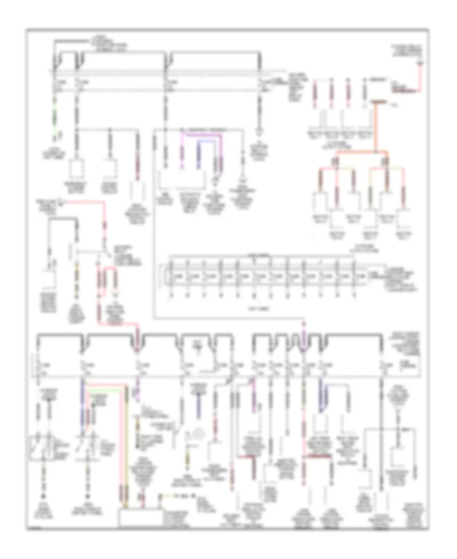
Электросхема блока предохранителей и реле (4 из 6) для Audi A4 2.0T Avant Quattro 2010
Электросхема блока предохранителей и реле (4 из 6) для Audi A4 2.0T Avant Quattro 2010 - Список элементов:
Электросхема блока предохранителей и реле (5 из 6) для Audi A4 2.0T Avant Quattro 2010
Электросхема блока предохранителей и реле (5 из 6) для Audi A4 2.0T Avant Quattro 2010 - Список элементов:
Электросхема блока предохранителей и реле (6 из 6) для Audi A4 2.0T Avant Quattro 2010
Электросхема блока предохранителей и реле (6 из 6) для Audi A4 2.0T Avant Quattro 2010 - Список элементов: