БЛОК ПРЕДОХРАНИТЕЛЕЙ И РЕЛЕ
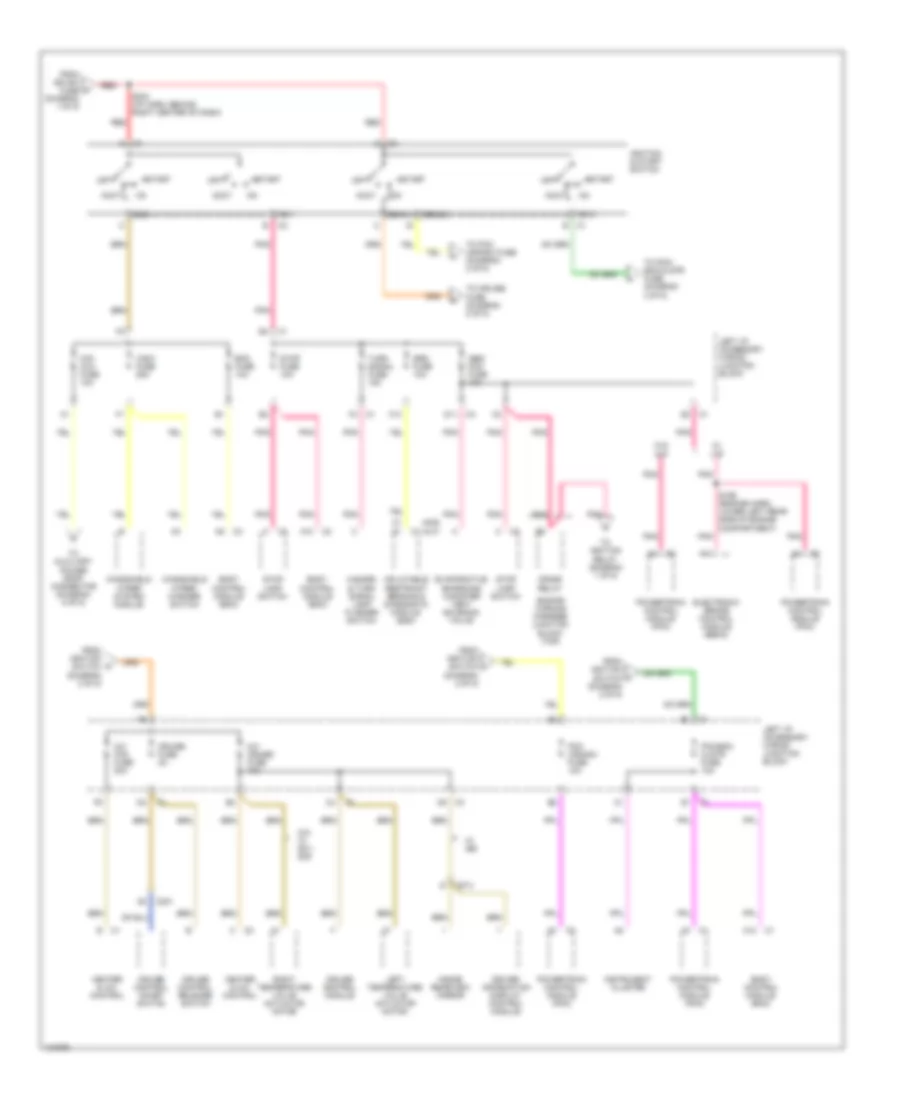
Электросхема блока предохранителей и реле (1 из 5) для Chevrolet Impala 2000
 https://portal-diagnostov.com/license.html
Automotive Electricians Portal FZCO
Automotive Electricians Portal FZCO
https://portal-diagnostov.com/license.html
https://portal-diagnostov.com/license.html
Automotive Electricians Portal FZCO
Automotive Electricians Portal FZCO
Электросхема блока предохранителей и реле (1 из 5) для Chevrolet Impala 2000 - Список элементов:
- (i/p harn, behind red
- Audio power booster (uq3)
- B10
- Battery
- Cd player (uq3)
- Circuit breaker 1 30a
- Circuit breaker 2 30a (seo)
- Circuit breaker 3 50a
- Cooling fans fuse 60a
- D11
- Electronic brake control module (ebcm)
- Engine wiring harness junction block (bottom)
- Engine wiring harness junction block (top)
- F nca
- F10
- F11
- From crank o relay (diagram 2 of 5)
- Fuse 15a
- Fuse block (seo) (rpo 9c1/9c6)
- Fusible link (5 ga-rust)
- G202 (behind left side of dash, on right side of brake pedal bracket)
- Generator
- Htd mir fuse 10a
- Ign sw fuse 60a
- Ignition relay
- Left i/p accessory wiring junction block
- Left i/p fuse 60a
- Left outside rearview mirror
- Left spot lamp
- Nca
- Pnk
- Radio
- Radio antenna module
- Radio fuse 15a
- Rear defog circuit breaker 30a
- Rear defog relay
- Red
- Remote battery stud
- Right i/p 1 fuse 60a
- Right i/p 2 fuse 60a
- Right i/p accessory wiring junction block
- Right of dash, near bcm breakout) s244
- Right outside rearview mirror
- Right spot lamp
- S174
- Starter motor
- To air pmp rly fuse (diagram 3 of 5)
- To engine wiring harness junction block (top) (diagram 3 of 5)
- To engine wiring harness junction block (top) (diagram 5 of 5)
- To fan 1 cont fuse (diagram 3 of 5)
- To ignition switch (diagram 2 of 5)
- To left i/p accessory wiring junction block (diagram 3 of 5)
- To right i/p accessory wiring junction block (diagram 4 of 5)
- To right i/p accessory wiring junction block (diagram 5 of 5)
- To splice s177 (diagram 3 of 5)
- U/hood fuse 60a
- W/ nc1
- Wiring harness junction block (seo) (9c1/9c6)
Электросхема блока предохранителей и реле (2 из 5) для Chevrolet Impala 2000
Электросхема блока предохранителей и реле (2 из 5) для Chevrolet Impala 2000 - Список элементов:
- (aj7)
- (ak5)
- A/c cruise fuse 10a
- A/c fan fuse 20a
- A10
- A11
- A12
- Abs/ pcm fuse 10a
- Acc
- Accy
- Bcm fuse 10a
- Body control module (bcm)
- C201
- C373
- Cig/ aux fuse 10a
- Crank
- Crank relay
- Cruise control module
- Cruise control on/off switch
- Cruise control release switch
- Cruise fuse 2a
- D11
- Driver information display control module
- Electronic brake control module (ebcm)
- Engine wirning harness junction block (top)
- Evaporative emissions canister vent solenoid valve
- F10
- From ign sw fuse (diagram 1 of 5)
- From ignition switch (diagram 2 of 5)
- Hazard & turn signal lamp flasher switch
- Heater & a/c control
- Ign 0
- Ign 1
- Ign 3
- Ignition & start switch
- Inflatable restraint sensing & diagnostic module (sdm)
- Inside rearview mirror
- Instrument cluster
- Left i/p accessory wiring junction block
- Left temperature valve actuator motor
- N/a w/ 9c1/ 9c6
- Off
- Pcm (crank) fuse 10a
- Pcm/bcm clstr fuse 10a
- Pnk
- Powertrain control module (pcm)
- Red
- Right temperature valve actuator motor
- S169 (engine harn, lower left rear side of engine compartment)
- S234 (i/p harn, behind right center of dash)
- Srs fuse 10a
- Start
- Stop fuse 10a
- Stop lamp switch
- To auxiliary power drop connector (diagram 5 of 5)
- To cruise fuse (diagram 2 of 5)
- To ignition relay (diagram 1 of 5)
- To pcm (crank) fuse (diagram 2 of 5)
- To pcm/ bcm/clstr fuse (diagram 2 of 5)
- Turn signal fuse 15a
- W/ jl9
- W/ u68
- W/o jl9
- Windshield wiper system module
- Windshield wiper/ washer switch
- Wsw fuse 25a
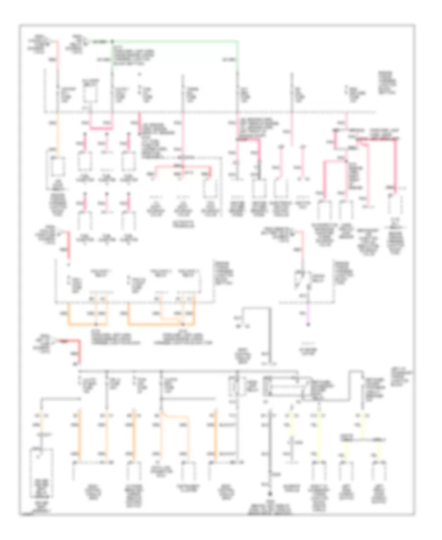
Электросхема блока предохранителей и реле (3 из 5) для Chevrolet Impala 2000
Электросхема блока предохранителей и реле (3 из 5) для Chevrolet Impala 2000 - Список элементов:
- (forward lamp harn, near left headlamp)
- 1-2 shift solenoid valve
- 2-3 shift solenoid valve
- A c435
- A.i.r. rly relay
- A/c cmpr relay
- A/c rly (coil) fuse 10a
- A12
- Air pmp rly fuse 30a
- Air pump relay
- Automatic transaxle
- B10
- Block (bottom))
- Body control module (bcm)
- C1 e11
- C11
- C113
- C12 c1
- C3 d1
- C311
- Clstr/ bcm fuse 10a
- Crank relay
- Data link connector (dlc)
- Dfi mdl fuse 15a
- Dr lk fuse 20a
- Driver heated seat relay module
- Driver seat assembly
- E1 c3
- Electronic ignition control module
- Eng devices fuse 10a
- Engine wiring harness junction block (bottom)
- Engine wiring harness junction block (top)
- Engine wirning harness junction block (top)
- Evaporative emissions canister purge solenoid valve
- F11
- F12
- Fan 1 cont fuse 25a
- Fan 2 & 3 cont fuse 25a
- Fan cont 1 relay
- Fan cont 2 relay
- Fan cont 3 relay
- From cooling fans fuse (diagram 1 of 5)
- From ign relay (diagram 1 of 5)
- From left i/p fuse (diagram 1 of 5)
- From remote battery stud e (diagram 1 of 5)
- From u/hood 2 fuse (diagram 1 of 5)
- Fuel inj fuse 15a
- Fuel injector
- G202 (behind left side of dash, on left side of brake pedal bracket)
- Head- lamp relay
- Heated oxygen sensor 1 (ho2s)
- Heated oxygen sensor 2 (ho2s)
- Ignition coil
- Impala
- Instrument cluster
- L36
- L36: (engine harn, left rear of engine) la1: (engine harn, left front of engine compt) s157
- La1
- Left front door window switch
- Left i/p accessory wiring junction block
- Left side window switch
- Lh htd st/bcm fuse 15a
- Mass airflow (maf) sensor
- Monte carlo
- Nc1,nc8
- Nca
- Nf2
- Outside rearview mirror remote control switch
- Oxy sen fuse 15a
- Pnk
- Pnk l36: (engine harn, engine near iat sensor) s109 la1: (fuel injector jumper harn, near fuel injector 1)
- Pnk s130
- Pwr mir fuse 2a
- Red
- Retained accessory power (rap) relay
- Retained accsry pwr brkr circuit breaker 30a
- Right i/p accessory wiring junction block (monte carlo)
- S115 red
- S131 (engine harn, right front of engine)
- S132 (forward lamp harn, inside engine wiring harness junction block (top)
- S179 (forward lamp harn, inside engine wiring harness junction block)
- S236
- Secondary air injection vacuum regulator solenoid valve
- Starter motor
- Sunroof module
- Tcc pwm solenoid valve
- Trans sol fuse 10a
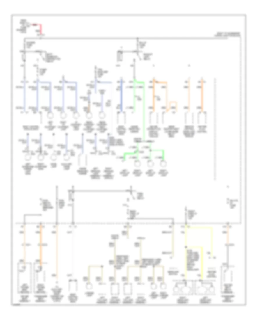
Электросхема блока предохранителей и реле (4 из 5) для Chevrolet Impala 2000
Электросхема блока предохранителей и реле (4 из 5) для Chevrolet Impala 2000 - Список элементов:
- (rear body harn, left front side of rear compt) s400
- A11
- A12 c3
- Auxiliary dome lamp
- B/u lp fuse 10a
- Backup lamp relay
- Batt rundown protection relay
- Body control module (bcm)
- C1 d4
- C3 e8
- C311
- C312
- C400
- D10
- Dic/rke fuse 10a
- Dome lamp
- Driver information display control module
- Driver seat assembly
- E3 c1
- E5 c3
- F1 c1
- F12
- F4 c1
- From right i/p 1 fuse (diagram 1 of 5)
- Front park lp fuse 15a
- H10
- H11
- H12
- Headlamp switch
- Heated seat relay module
- Heater & a/c control
- I/p compart- ment lamp
- Impala
- Inside rearview mirror
- Ip brp fuse 10a
- K10
- K11
- K12
- L10
- Left back-up lamp
- Left headlamp assembly
- Left i/p courtesy lamp
- Left license lamp
- Left power seat switch
- Left reading lamp assembly (impala)
- Left sunshade mirror lamp (dh6)
- Left taillamp assembly
- License lamp
- Monte carlo
- N10
- Nca
- Of rear compt) s400
- Park lamp relay
- Passenger seat assembly
- Pwr drop fuse 15a
- Pwr seats circuit breaker 30a
- Rear compart- ment courtesy lamp
- Rear compartment lid release relay (seo)
- Rear park lp fuse 15a
- Red
- Remote control door lock receiver (rcdlr)
- Rh htd st fuse 15a
- Right back-up lamp
- Right front side of roof)
- Right headlamp assembly
- Right i/p accessory wiring junction block
- Right i/p courtesy lamp
- Right license lamp
- Right power seat switch
- Right reading lamp assembly (impala)
- Right sunshade (dh6)
- Right taillamp assembly
- S176 (forward lamp harn, right side of engine compt, behind right headlamp)
- To auxiliary power drop connector (diagram 5 of 5)
- Trk/ roof brp fuse 15a
- W/ 9c1/ 9c6
- W/ c79
- W/ dd6
- W/ dh6
- W/ u68
- W/ ua6
- W/9c1/ 9c6
- W/o c79
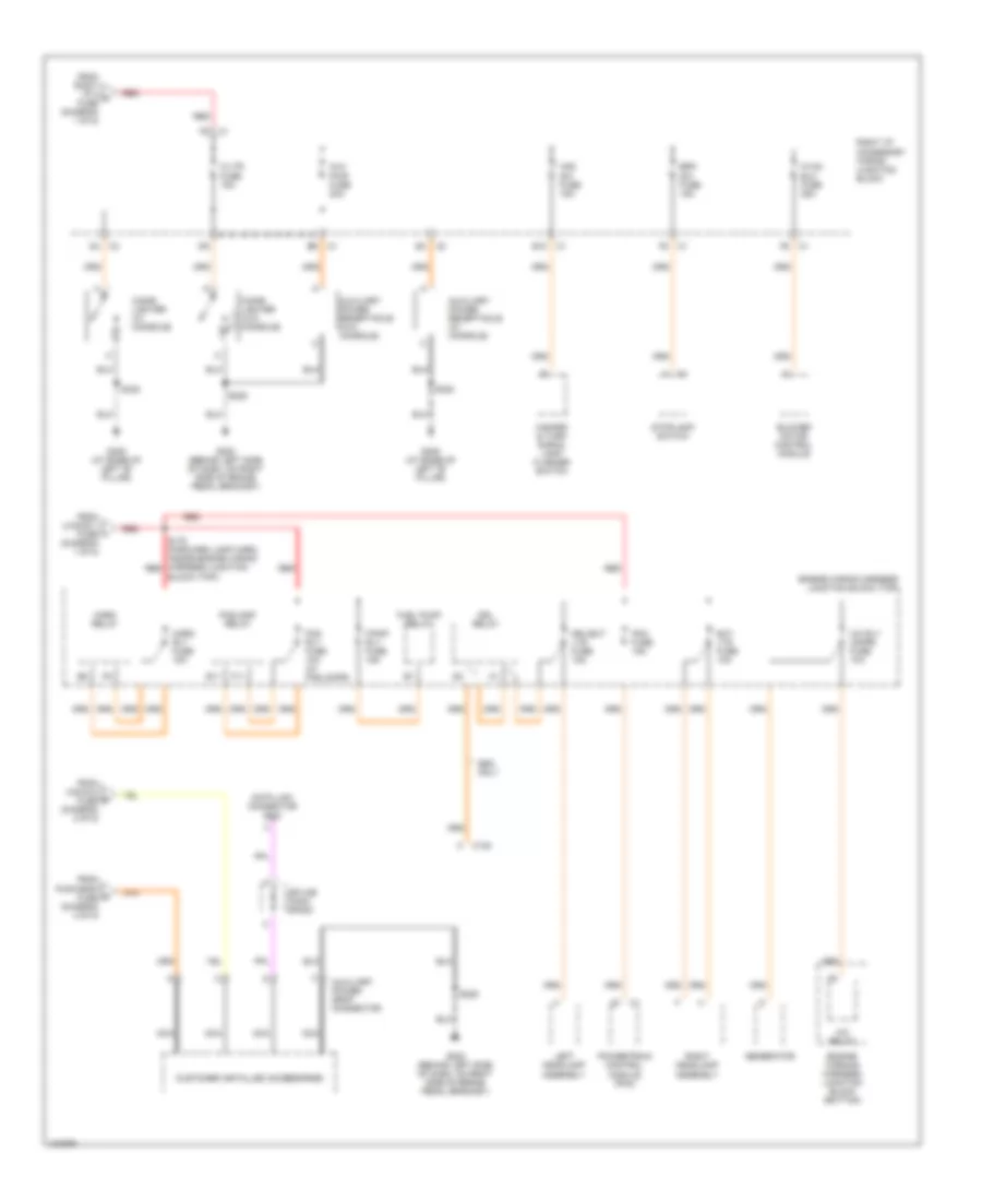
Электросхема блока предохранителей и реле (5 из 5) для Chevrolet Impala 2000
Электросхема блока предохранителей и реле (5 из 5) для Chevrolet Impala 2000 - Список элементов:
- A/c relay
- A/c rly (cmpr) fuse 10a
- Aux pwr fuse 20a
- Auxiliary power drop connector
- Auxiliary power receptacle (w/ console)
- Auxiliary power receptacle (w/o console)
- Block (top))
- Blower motor control module
- Brk sw fuse 15a
- C/ltr fuse 15a
- C122
- Cigar lighter (w/ console)
- Cigar lighter (w/o console)
- Customer installed accessories
- Data link connector (dlc)
- Drl relay
- Drl/ext lts fuse 15a
- E10
- E11
- Engine wiring harness junction block (top)
- Engine wirning harness junction block (bottom)
- Ext lts fuse 10a
- F/pmp rly fuse 15a
- F11
- Fog rly fuse 10a (w/ foglamps)
- Foglamp relay
- From cig/aux fuse (diagram 2 of 5)
- From pwr drop fuse (diagram 4 of 5)
- From right i/p 2 fuse (diagram 1 of 5)
- From u/hood 1 fuse (diagram 1 of 5)
- Fuel pump relay
- G202 (behind left side of dash, on right side of brake pedal bracket)
- G308 (at base of left "b" pillar)
- Generator
- Haz sw fuse 15a
- Hazard & turn signal lamp flasher switch
- Horn relay
- Horn rly fuse 15a
- Hvac blo fuse 25a
- Left headlamp assembly
- Nca
- Pcm fuse 15a
- Powertrain control module (pcm)
- Red
- Right headlamp assembly
- Right i/p accessory wiring junction block
- S178 (forward lamp harn, inside engine wiring harness junction red
- S229
- S320
- S338
- Seo only
- Splice pack sp205
- Stoplamp switch

 Čeština
 Dansk
Dansk Deutsch
 Ελληνικά
 English
 Español
 Suomi
Suomi Français
 Français
 עברית
עברית Hrvatski
 Magyar
 Italiano
 日本語
日本語 한국어
한국어 Nederlands
 Polski
 Português
 Português
 Română
 Русский
 Slovenčina
 Slovenščina
 Svenska
 Türkçe
 中文 (中国)