БЛОК ПРЕДОХРАНИТЕЛЕЙ И РЕЛЕ
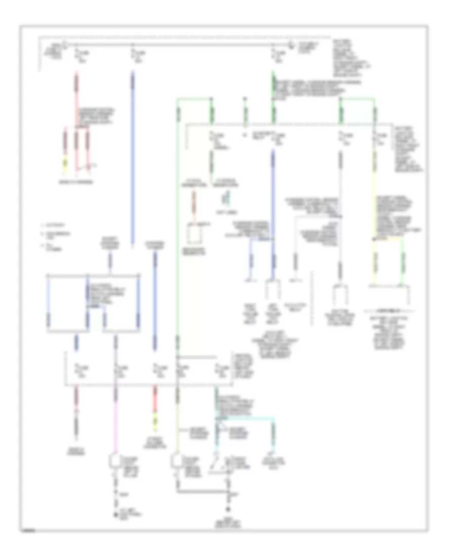
Электросхема блока предохранителей и реле (1 из 6) для Ford Econoline E150 2007

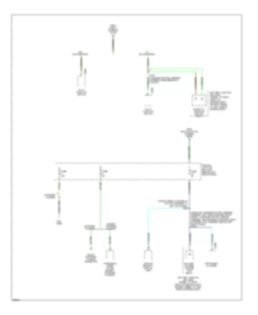
Электросхема блока предохранителей и реле (1 из 6) для Ford Econoline E150 2007 - Список элементов:
- (at right front of engine compt) battery junction box (bjb)
- (engine control sensor & fuel charge harness, in breakout to starter motor)
- (engine control sensor & fuel charge harness, in breakout to starter motor) s1052
- (engine control sensor & fuel charge harness, in breakout to starter motor) s1072
- (in starter relay to fuse junction panel harness, in breakout to battery) s1007
- (in starter relay/battery ground harness, in breakout to battery) s1073
- (in starter relay/battery ground harness, in breakout to battery) s1074
- (in starter relay/battery ground harness, in breakout to battery) s1076
- (near breakout to battery junction box) red s1075
- Abs test connector
- Battery
- Battery ii
- Battery junction box (bjb) (at left side of engine compt)
- Battery junction box (bjb) (at right front of engine compt)
- Blower motor relay
- C102a
- C102c
- C1104a
- C1104c
- C1251b
- C1273a
- C1273b
- Diesel
- Except diesel
- Fuel injector control module (ficm) power relay
- Fuel pump relay
- Fuse 20a
- Fuse 40a
- Fuse 50a
- Generator
- Glow plug control module (gpcm)
- Red
- Remote jump start terminal
- S1008 (in starter relay to fuse junction panel harness, in breakout to battery)
- S1051 (in breakout to starter motor)
- S1054 (in breakout to starter motor)
- S1055 (near breakout to left front of engine)
- S1056 (in breakout to starter motor)
- S1071
- S1073 (alternator rectifier system harness, red (near breakout to battery junction box)
- S191 (in alternator rectifier system harness, in breakout to battery)
- S192 (in alternator rectifier system harness, in breakout to battery)
- Secondary generator
- Starter motor
- To fuse 9 (diagram 2 of 6)
- W/ advance trac
- W/ dual generators
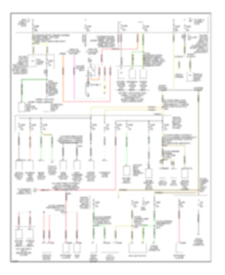
Электросхема блока предохранителей и реле (2 из 6) для Ford Econoline E150 2007
Электросхема блока предохранителей и реле (2 из 6) для Ford Econoline E150 2007 - Список элементов:
- (at left kick panel) g204
- (except diesel: in engine control sensor harness, near breakout to g101) (diesel: in engine control sensor harness, near breakout to battery junction box) s1034
- (except diesel: in engine sensor harness, at left front of engine compt) (diesel: in engine sensor harness, at right front of engine compt) s1028
- (except stripped chassis)
- (in engine control sensor harness, in breakout to auxiliary relay box 1) (except diesel) s186
- (in engine control sensor harness, in breakout to auxiliary relay box 1) s1019
- (in window regulator relay switch harness, near breakout ignition switch) s229
- (in window regulator relay switch harness, near left kick panel) s266
- (not used)
- A/c clutch relay
- All
- Auxiliary relay box 1 (diesel: at right front of engine compt) (except diesel: at left rear of engine compt)
- Battery junction box (bjb) (diesel: at right front of engine compt) (except diesel: at left side of engine compt)
- C1251a
- Central junction box (cjb) (behind left side of dash)
- Conversion
- Cutaway
- Data link connector (dlc)
- Daytime running lamps (drl) module (if equipped)
- Ends in harness
- Except stripped chassis
- From a fuse 13 (diagram 1 of 6)
- Front cigar lighter
- Fuse 10a (diesel)
- Fuse 15a
- Fuse 20a
- Fuse 30a
- Fuse 50a
- Fuse 60a
- G202 (behind left side of dash)
- Horn relay
- I/p body builder connector
- In engine control sensor harness, left rear side of engine compt) s2012
- Left turn trailer tow relay
- Others
- Power point (behind center of dash)
- Power point (behind left "b" pillar)
- Red
- Right turn trailer tow relay
- S145 (diesel) (in engine control sensor harness, near breakout to g106)
- S207
- S235
- Secondary generator
- Starter relay
- Stripped chassis
- To fuse 21 (diagram 3 of 6)
- Van
- W/ dual generators
- W/ single generators
Электросхема блока предохранителей и реле (3 из 6) для Ford Econoline E150 2007
Электросхема блока предохранителей и реле (3 из 6) для Ford Econoline E150 2007 - Список элементов:
- (diesel)
- (except diesel)
- (in engine control sensor harness, except diesel: left side of engine compt, diesel: right side of eng compt) s1033
- (in main harness, harness, at left side of dash)
- (in main harness, near breakout to audio unit s205
- (in main harness, near breakout to electronic flasher module) s282
- (in main harness, near breakout to g207) s219
- (in main harness, near breakout to main light switch) s276
- (in main harness, under left side of dash) s221
- (in window regulator relay switch harness, near breakout accelerator pedal postion switch) (w/ remote keyless entry) s261
- (in window regulator relay switch harness, near breakout to accelerator pedal position switch)
- (in window regulator relay switch harness, near breakout to brake pedal position switch)
- (not used)
- 16-way stripped chassis connector
- Audio unit
- Auxiliary battery relay
- Auxiliary relay box 2 (behind center of dash)
- Battery charge trailer tow relay
- Battery ii
- Battery junction box (bjb) (diesel: at right front of engine compt) (except diesel: at left side of engine compt)
- Battery saver relay
- Brake pedal position switch
- C.b. 20a
- C1381b
- C175b
- C202a
- C202b
- C2113a
- C220b
- C240
- C280
- Central junction box (cjb) (behind left side of dash)
- Cutaway
- Diesel
- Driver side front seat adjust switch
- Ends in harness
- Evap canister vent valve (gas)
- Except cutaway
- Except stripped chassis
- Exterior rear view mirror switch
- From b fuse 18 (diagram 2 of 6)
- Front passenger window/ door lock switch
- Fuse
- Fuse 10a
- Fuse 15a
- Fuse 20a
- Fuse 30a
- Fuse 40a
- Fuse 50a
- Fuse 5a
- Fuse 60a
- Fuse fuse 30a 30a
- Gasoline w/ auxiliary battery
- Gasoline w/o auxiliary battery
- I/p body builder connector
- Instrument cluster
- Interior lamp relay
- Main light switch
- Master window/ door lock/ unlock switch
- Multi- function switch
- Nca
- Parking lamp trailer tow relay
- Pcm power relay
- Powertrain control module (pcm)
- Rear a/c blower speed relay 1
- Rear doors door lock switch
- Reversing lamp trailer tow relay
- S1021 (in engine control sensor harness, (left side of engine compt)
- S1027
- S1032 (in engine control sensor harness, except diesel: left side of engine compt, diesel: right side of engine compt)
- S218
- S225
- S237
- S291
- Stripped chassis
- To accessory delay relay (diagram 4 of 6)
- To fuse 15 (diagram 4 of 6)
- To multi- function switch (diagram 6 of 6)
- Traction control switch
- Vehicle security module (vsm)
- Vehicle security module (vsm) (w/ rke)
- W/ auxiliary a/c
- Windshield wiper motor
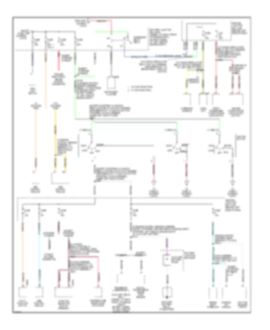
Электросхема блока предохранителей и реле (4 из 6) для Ford Econoline E150 2007
Электросхема блока предохранителей и реле (4 из 6) для Ford Econoline E150 2007 - Список элементов:
- (center of driver's door) s501
- (engine control harness, near breakout to c219) s2013
- (except stripped: in window regulator relay switch harness, near breakout to igniton switch, stripped: in main harness, under left end of dash) s230
- (except stripped: in window regulator relay switch harness, near breakout to igniton switch, stripped: in main harness, under left end of dash) s280
- (in engine control sensor harness, except stripped: center rear of engine compt, stripped: left side of engine compt) (w/ auxiliary battery) s113
- (in engine control sensor harness, in breakout to abs control module) s177
- (in main harness, near breakout to function selector switch assembly) s203
- (in window regulator relay switch harness, (at left end of dash) s245
- (in window regulator relay switch harness, (near breakout to accelerator pedal postion switch)
- (in window regulator relay switch harness, near breakout to brake pedal position switch)
- (in window regulator relay switch harness, near breakout to temp blend door actuator) s242
- (main harness, near breakout to main light switch) s201
- 40a
- Abs control module
- Acc
- Accessory delay relay
- At left side of engine compt)
- Audio unit
- Auxiliary battery diode
- Auxiliary battery relay (if equipped)
- Auxiliary relay box 1 (diesel: at right front of engine compt) (except diesel: at left side of engine compt)
- Battery junction box (bjb)
- Battery junction box (bjb) (diesel: at right front of engine compt) (except diesel: at left side of engine compt)
- Brake shift interlock
- C.b. 20a
- C202a
- C220b
- C240
- C294a
- Central junction box (cjb) (behind left side of dash)
- Daytime running lights
- Digital transmission range (dtr) sensor
- Except stripped chassis
- Except torqshift
- From e fuse 14 (diagram 3 of 6)
- From s291 f (diagram 3 of 6)
- Front passenger window/door lock switch
- Function selector switch assembly
- Fuse 10a
- Fuse 15a
- Fuse 30a
- Fuse 5a
- Fuse 60a
- I/p body builder connector
- Ignition switch
- Instrument cluster
- Lock
- Main light switch
- Master window/door lock/unlock switch
- Multi- function switch
- Off
- Overhead console
- Parking aid module
- Red
- Reversing lamp relay
- Run
- S227
- S236
- Start
- Stripped chassis
- Temperature blend door actuator
- To fuse 14 (diagram 5 of 6)
- To fuse 33 (diagram 5 of 6)
- To fuse 9 (diagram 6 of 6)
- Torqshift
- Trailer electronic brake control connector
- W/ advance trac
- W/ overhead console
- W/ power door locks
- W/o advance trac
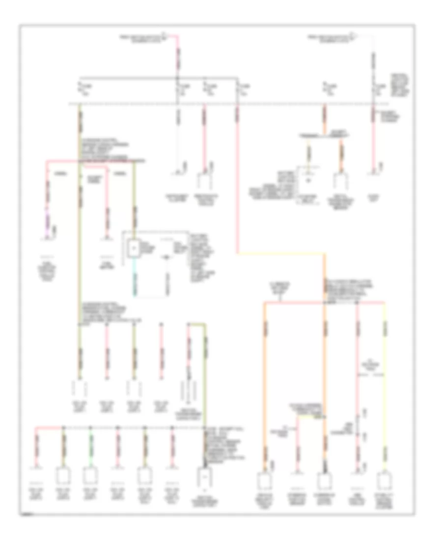
Электросхема блока предохранителей и реле (5 из 6) для Ford Econoline E150 2007
Электросхема блока предохранителей и реле (5 из 6) для Ford Econoline E150 2007 - Список элементов:
- (6.8l)
- (diesel: at right front of engine compt) (except diesel: at left side of engine compt)
- (except 6.8l)
- (in engine control sensor & fuel charge harness, in breakout to heated positive crankcase ventilation valve s161
- (in engine control sensor wiring harness, at left rear of engine compt) s127 (stripped chassis) s1065 (except stripped chassis)
- (in main harness, in breakout to cigar ligher) s260
- (in window regulator relay switch harness, near breakout to accelerator pedal position switch) s216
- Abs
- Audio unit
- Battery junction box (bjb)
- Battery junction box (bjb) (diesel: at right front of engine compt) (except diesel: at left side of engine compt)
- C126
- C1388c
- C155
- C203b
- C220a
- C240
- C310a
- Cancel switch
- Central junction box (cjb) (behind left side of dash)
- Coil on plug (cop) 1
- Coil on plug (cop) 10 (6.8l)
- Coil on plug (cop) 2
- Coil on plug (cop) 3
- Coil on plug (cop) 4
- Coil on plug (cop) 5
- Coil on plug (cop) 6
- Coil on plug (cop) 7
- Coil on plug (cop) 8
- Coil on plug (cop) 9 (6.8l)
- Control module
- Control sensor cluster
- Diesel
- Digital transmission range (dtr) sensor
- Except diesel
- Except stripped chassis
- Except torqshift
- From ignition switch k (diagram 4 of 6)
- From ignition switch l (diagram 4 of 6)
- Fuel heater
- Fuel injector control module (ficm)
- Fuse 10a
- Fuse 15a
- Fuse 5a
- Ignition transformer capacitor 1
- Ignition transformer capacitor 2
- Instrument cluster
- Nca
- Overdrive
- Pcm power diode
- Pcm power relay
- Position sensor
- Restraints control module
- S156
- S162 (in engine control sensor & fuel charge harness, near breakout to throttle position sensor)
- Security module (vsm)
- Stability
- Starter relay
- Steering
- Tan/red
- Test connector
- Torqshift
- Vehicle
- W/ advance trac
- W/ remote keyless entry
Электросхема блока предохранителей и реле (6 из 6) для Ford Econoline E150 2007
Электросхема блока предохранителей и реле (6 из 6) для Ford Econoline E150 2007 - Список элементов:
- (gasoline: in engine control sensor harness, left side of engine compt, diesel: in engine control sensor harness, center rear of engine compt, stripped: main harness, behind left side of dash) s1022
- (window regulator relay switch harness, at left kick panel) s246
- 16-way stripped chassis connector
- Battery charge trailer tow relay
- Battery junction box (bjb) (diesel: at right front of engine compt) (except diesel: at left side of engine compt)
- C202a
- C220b
- Central junction box (cjb) (behind left side of dash)
- Except stripped chassis
- From fuse 11 (diagram 3 of 6)
- From ignition switch (diagram 4 of 6)
- Fuse 15a
- Fuse 5a
- Instrument cluster
- Multi- function switch
- Not used
- S105 (in engine control sensor harness, near breakout to g101)
- Stability/ traction control relay
- Stripped chassis
- Vehicle security module (vsm)
- W/ advancetrac
- W/o advancetrac
- Windshield wiper motor (except stripped chassis)