БЛОК ПРЕДОХРАНИТЕЛЕЙ И РЕЛЕ
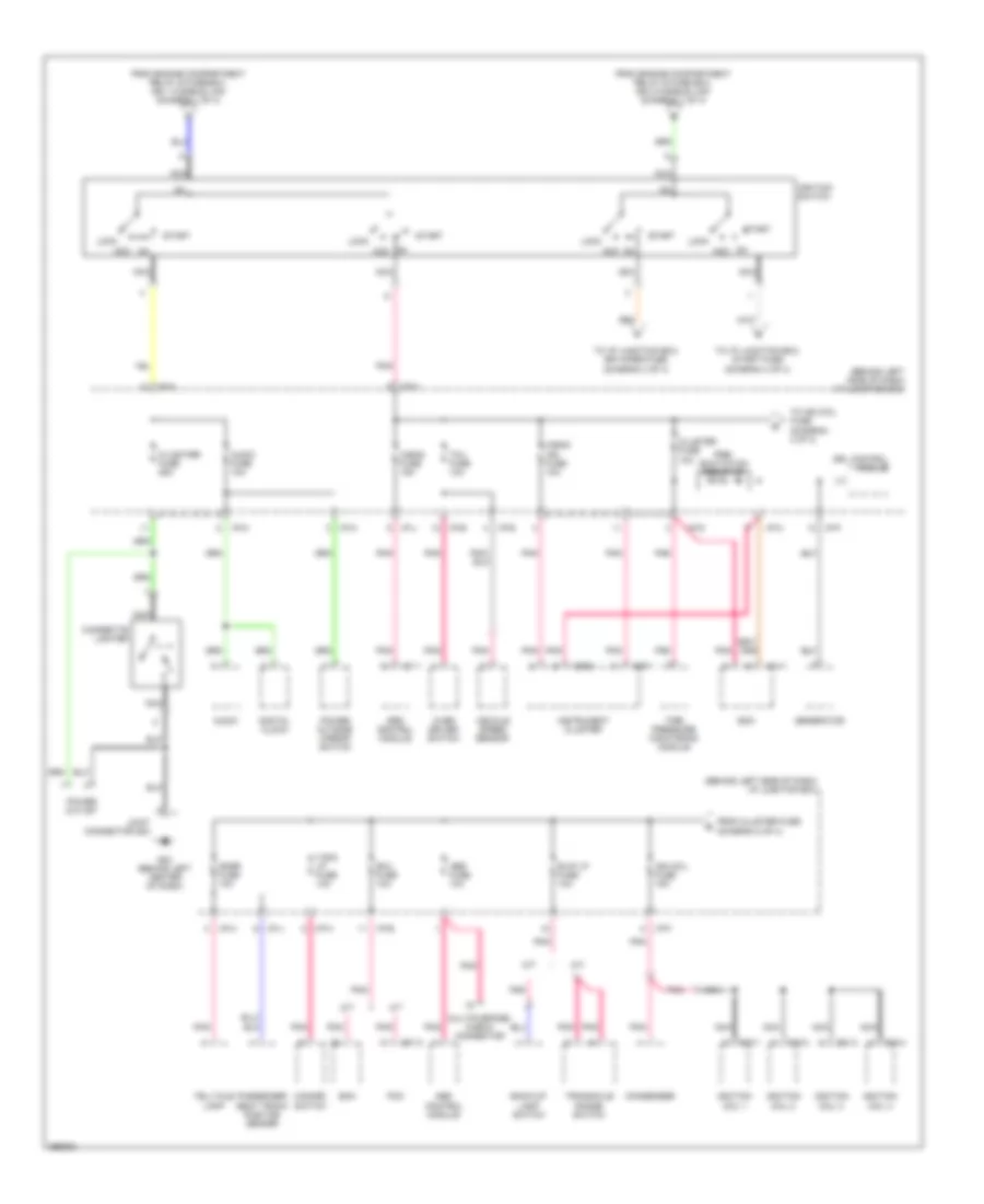
Электросхема блока предохранителей и реле (1 из 4) для Hyundai Accent SE 2007

Электросхема блока предохранителей и реле (1 из 4) для Hyundai Accent SE 2007 - Список элементов:
- (diagram 1 of 4)
- (on left side of engine compartment) engine compartment relay & fuse box
- A/con 1 fusible link 10a
- A/con relay
- A/t
- Abs 1 fusible link 40a
- Abs 2 fusible link 40a
- Abs control module
- Batt 1 fusible link 50a
- Batt 2 fusible link 30a
- Battery
- Blower fusible link 40a
- Blower relay
- Burglar alarm horn relay
- C01-1
- C01-2
- C13-1
- C13-2
- C13-3
- C13-4
- Camshaft position sensor
- Canister close valve
- Cond fusible link 30a
- Condenser fan relay 1
- Condenser fan relay 2
- Cvvt oil control valve
- Ecm
- Ecm (m/t)
- Ecu a fusible link 30a
- Ecu b fuse 10a
- Ecu c fuse 20a
- From ecu a fusible link a
- From main relay b
- Fuel pump relay
- Generator
- Horn fuse 10a
- Horn relay
- I/p junction box (behind left side of dash)
- I/p-e
- Icm relay box (behind left center of dash)
- Idle speed control actuator
- Ign 1 fusible link 30a
- Ign 2 fusible link 40a
- Inj fuse 15a
- Injector
- Joint connector c12 (in engine compt relay & fuse box)
- M/t
- Main fusible link 125a
- Main relay
- Motor
- Multipurpose check connector
- Nca
- Oxygen sensor (down)
- Oxygen sensor (up)
- P/wdw fusible link 30a
- Pcm
- Pcm (a/t)
- Power window relay
- Purge control solenoid valve
- Rad fusible link 30a
- Radiator fan relay
- Red
- Snsr fuse 10a
- Start
- Start relay
- To batt 1 fusible link (diagram 1 of 4)
- To ecu c fuse (diagram 1 of 4)
- To i/p junction box, hazard fuse (diagram 4 of 4)
- To i/p junction box, htd glass fuse (diagram 3 of 4)
- To ignition switch (diagram 2 of 4)
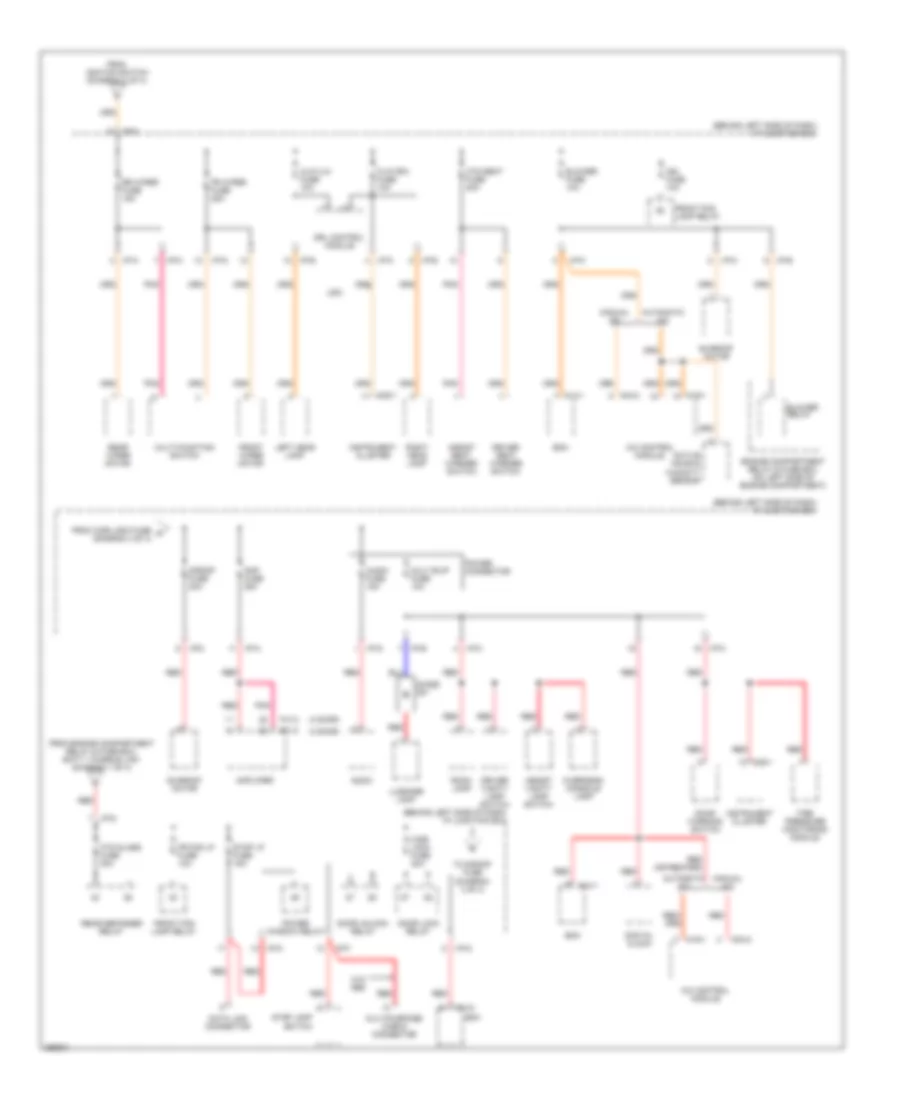
Электросхема блока предохранителей и реле (2 из 4) для Hyundai Accent SE 2007
Электросхема блока предохранителей и реле (2 из 4) для Hyundai Accent SE 2007 - Список элементов:
- (behind left side of dash) i/p junction box
- A/bag fuse 15a
- A/bag ind fuse 10a
- A/t
- Abs control module
- Abs fuse 10a
- Acc
- Audio
- Audio fuse 10a
- B/up lp fuse 10a
- Back-up lamp switch
- Bcm
- C/lighter fuse 25a
- C01-2
- C10-1
- C10-2
- C10-3
- C10-4
- Cigarette lighter
- Cluster fuse 10a
- Condenser
- Digital clock
- Drl control module
- Ecm
- Ecu fuse 10a
- From cluster fuse (diagram 2 of 4)
- From engine compartment relay & fuse box, ign 1 fusible link (diagram 1 of 4)
- From engine compartment relay & fuse box, ign 2 fusible link (diagram 1 of 4)
- G03 (behind left center of dash)
- Generator
- Hazard switch
- I/p-a
- I/p-b
- I/p-e
- I/p-f
- I/p-g
- I/p-h
- I/p-j
- I/p-m
- I01-1
- Ign coil fuse 15a
- Ignition coil 1
- Ignition coil 2
- Ignition coil 3
- Ignition coil 4
- Ignition switch
- Instrument cluster
- Joint connector g03
- Lock
- Lock acc
- M/t
- M09-1
- M09-2
- M14-1
- Multipurpose check connector
- Nca
- Over driver switch
- Passenger seat track position sensor
- Pcm
- Pnk
- Power outlet
- Power outside mirror switch
- Pre- excitation resistor
- Snsr fuse 10a
- Srs control module
- Start
- T/sig lp fuse 10a
- Tcu fuse 10a
- Telltale lamp
- Tire pressure monitoring module
- To i/p junction box, rr wiper fuse (diagram 3 of 4)
- To i/p junction box, start fuse (diagram 4 of 4)
- To ign coil fuse (diagram 2 of 4)
- Transaxle range switch
- Vehicle speed sensor
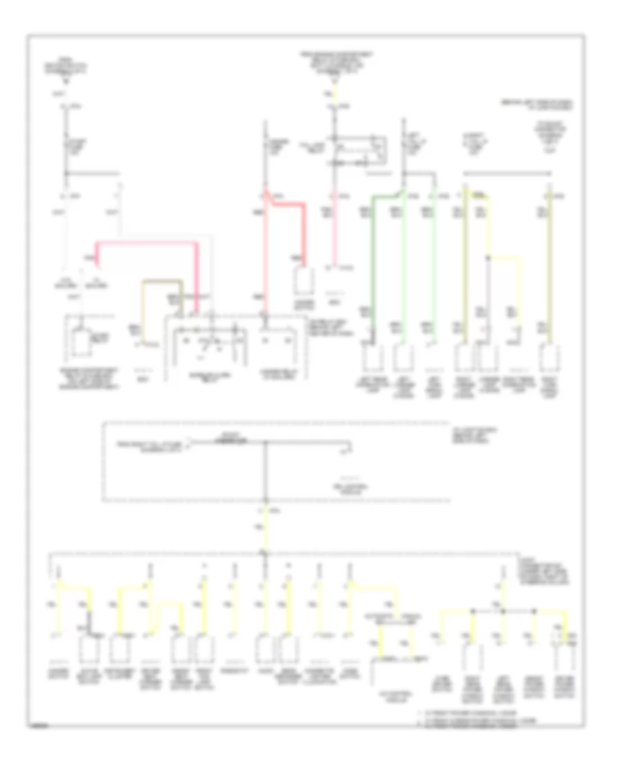
Электросхема блока предохранителей и реле (3 из 4) для Hyundai Accent SE 2007
Электросхема блока предохранителей и реле (3 из 4) для Hyundai Accent SE 2007 - Список элементов:
- (3 door)
- (4 door)
- (behind left side of dash) i/p junction box
- A/c control module
- Active incar & humidity sensor
- Amp fuse 25a
- Amplifier
- Assist seat warmer switch
- Assist vanity lamp switch
- Audio
- Audio fuse 15a
- Automatic a/c
- Bcm
- Blower fuse 10a
- Blower relay
- C/dr lock fuse 20a
- Data link connector
- Digital clock
- Diode z01
- Door lock relay
- Door unlock relay
- Door warning switch
- Driver seat warmer switch
- Driver vanity lamp switch
- Drl control module
- Engine compartment relay & fuse box (on left side of engine compartment)
- F01-2
- F41-2
- Fr fog lp fuse 10a
- Fr wiper fuse 25a
- From c/dr lock fuse k (diagram 3 of 4)
- From engine compartment relay & fuse box, batt 1 fusible link (diagram 1 of 4)
- From ignition switch (diagram 2 of 4)
- Front fog lamp relay
- Front wiper motor
- H/lp (lh) fuse 10a
- H/lp (rh) fuse 10a
- Htd glass fuse 30a
- Htd seat fuse 20a
- I/p-a
- I/p-b
- I/p-c
- I/p-d
- I/p-e
- I/p-f
- I/p-g
- I/p-k
- I/p-m
- I/p-n
- Ign fuse 10a
- Instrument cluster
- Left head lamp
- Luggage lamp
- M04-2
- M09-1
- M14-1
- M14-2
- M16-1
- Manual a/c
- Mult b/up fuse 10a
- Multi-function switch
- Multipurpose check connector
- Overhead console lamp
- Pnk
- Power connector
- Power window relay
- Rear defogger relay
- Rear wiper motor
- Red
- Right head lamp
- Room lamp
- Rr wiper fuse 15a
- S/roof fuse 20a
- Stop lamp switch
- Stop lp fuse 15a
- Sunroof motor
- Tire pressure monitoring module
- To s/roof fuse (diagram 3 of 4)
- Usa
- W/o abs
Электросхема блока предохранителей и реле (4 из 4) для Hyundai Accent SE 2007
Электросхема блока предохранителей и реле (4 из 4) для Hyundai Accent SE 2007 - Список элементов:
- (behind left side of dash) i/p junction box
- 87a
- A/c control module
- Assist power window switch
- Assist seat warmer switch
- Audio
- Automatic a/c
- Bcm
- Burglar alarm relay
- Cigarette lighter illumination
- D04
- D05
- Driver power window switch
- Driver seat warmer switch
- Drl control module
- Engine compartment relay & fuse box (on left side of engine compartment)
- From engine compartment relay & fuse box, batt 2 fusible link (diagram 1 of 4)
- From ignition switch (diagram 2 of 4)
- From right tail lp fuse l (diagram 4 of 4)
- Front fog lamp switch
- Glove box lamp switch
- Hazard fuse 10a
- Hazard relay (w/ b/alarm)
- Hazard switch
- I/p junction box (behind left side of dash)
- I/p-b
- I/p-e
- I/p-f
- I/p-g
- I/p-n
- Icm relay box (behind left center of dash)
- Instrument cluster
- Joint connector m27 (under left side of dash, right of steering column)
- Left license lamp (3 door)
- Left rear combination lamp
- Left rear power window switch
- Left tail lp fuse 10a
- Left turn signal lamp
- License lamp (4 door)
- M04-2
- M09-1
- M10-1
- M14-2
- M16-1
- M66-2
- Manual a/c
- Mode switch
- Nca
- Over driver switch
- Pnk
- Rear defogger switch
- Red
- Rheostat
- Right license lamp (3 door)
- Right rear combination lamp
- Right rear power window switch
- Right tail lp fuse 10a
- Right turn signal lamp
- Shunt connector
- Start fuse 10a
- Start relay
- Tail lamp relay
- To shunt connector (diagram 4 of 4)
- W/ b/alarm
- W/ front & rear power windows, 4 door w/ front power windows, 3 door
- W/ front power windows, 4 door
- W/o b/alarm