БЛОК ПРЕДОХРАНИТЕЛЕЙ И РЕЛЕ
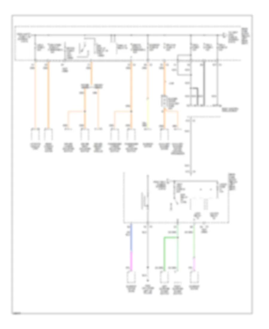
Электросхема блока предохранителей и реле (1 из 5) для Isuzu Ascender S 2006

Электросхема блока предохранителей и реле (1 из 5) для Isuzu Ascender S 2006 - Список элементов:
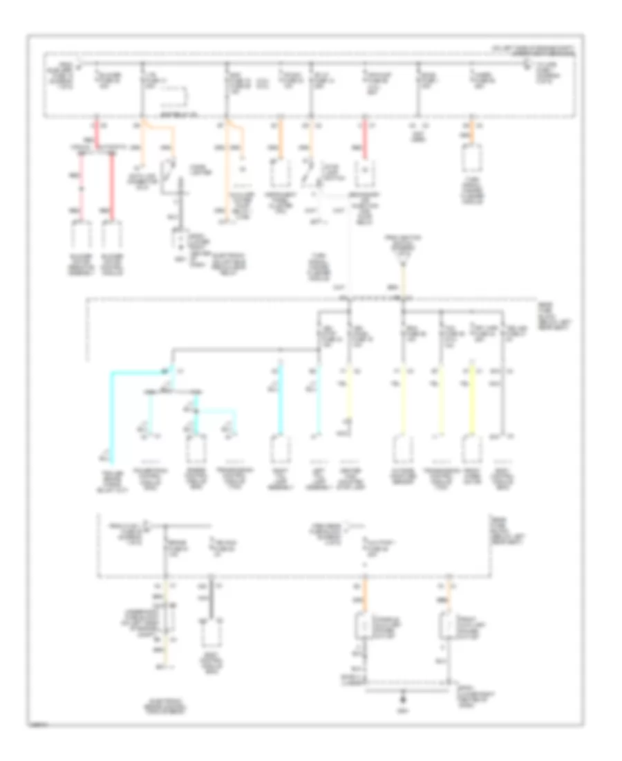
Электросхема блока предохранителей и реле (2 из 5) для Isuzu Ascender S 2006
Электросхема блока предохранителей и реле (2 из 5) для Isuzu Ascender S 2006 - Список элементов:
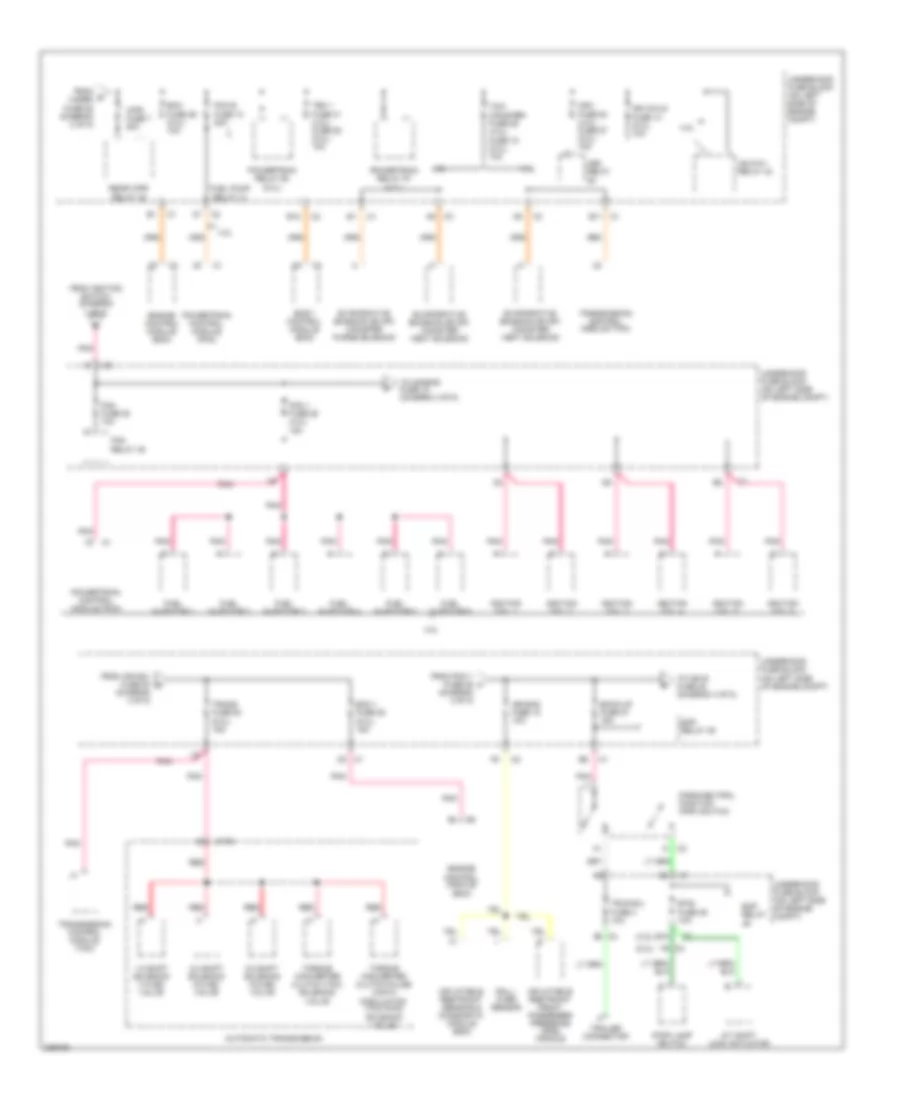
Электросхема блока предохранителей и реле (3 из 5) для Isuzu Ascender S 2006
Электросхема блока предохранителей и реле (3 из 5) для Isuzu Ascender S 2006 - Список элементов:
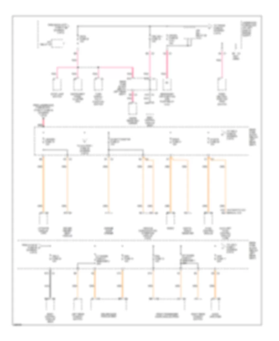
Электросхема блока предохранителей и реле (4 из 5) для Isuzu Ascender S 2006
Электросхема блока предохранителей и реле (4 из 5) для Isuzu Ascender S 2006 - Список элементов:
Электросхема блока предохранителей и реле (5 из 5) для Isuzu Ascender S 2006
Электросхема блока предохранителей и реле (5 из 5) для Isuzu Ascender S 2006 - Список элементов: