БЛОК ПРЕДОХРАНИТЕЛЕЙ И РЕЛЕ
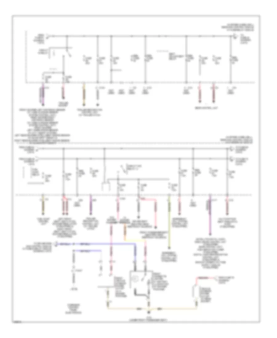
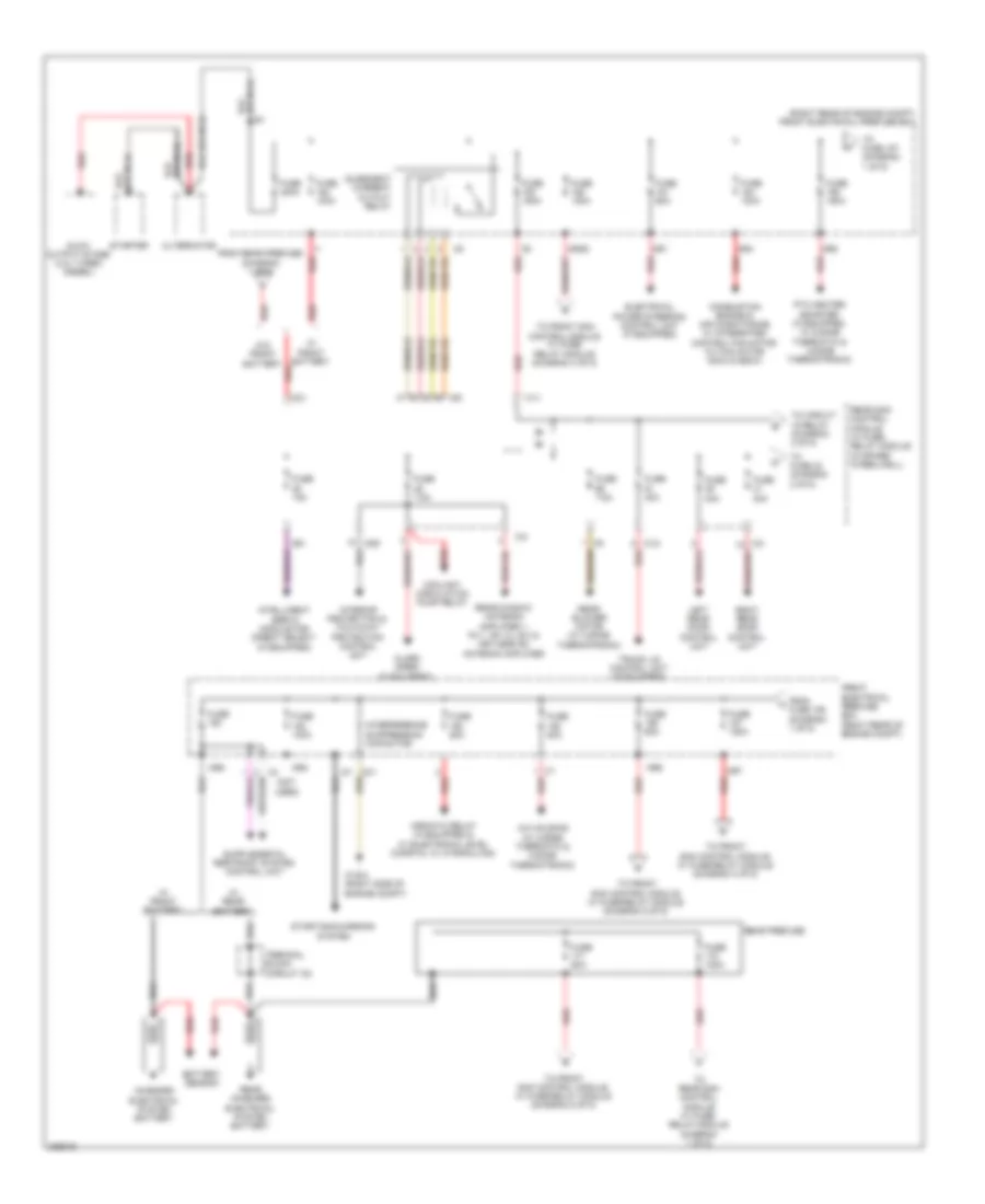
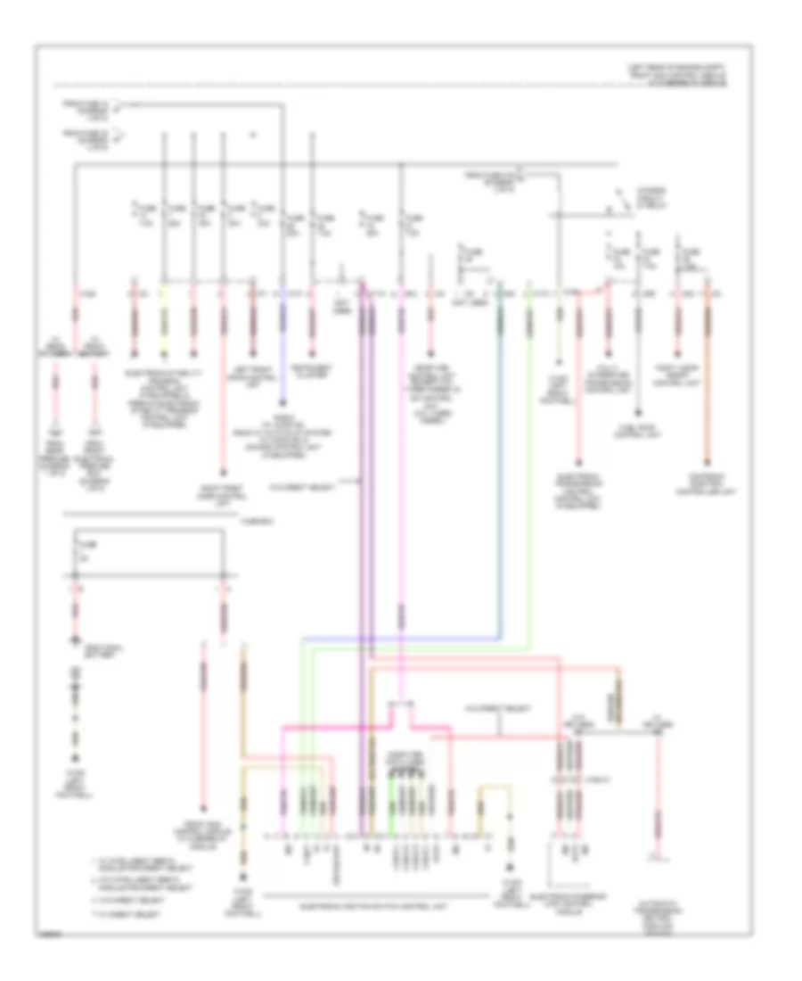
Электросхема блока предохранителей и реле, Купе (1 из 5) для Mercedes-Benz E350 2012

Электросхема блока предохранителей и реле, Купе (1 из 5) для Mercedes-Benz E350 2012 - Список элементов:
- (not used)
- (right rear of engine compt) front electrical prefuse box
- 18m
- 200a (or 400a)
- 60a
- A/c housing (w/ thermatic & thermotronic)
- Additional battery relay (w/ eco start stop function)
- Airscarf system control unit (w/ heated seats & seat ventilation)
- Alternator
- Antenna amplifier
- Battery sensor
- C116
- C117
- C126
- C127
- C128
- C30
- C30g
- C3i
- C8d
- C9i
- Ci2
- Cim1
- Combustion engine & air conditioning w/ integrated control fan motor
- Decoupling relay
- Driver seat control unit
- Electrical power steering control unit (if equipped)
- From fuse a (diagram 1 of 5)
- Front electrical prefuse box (right rear of engine compt)
- Front passenger seat control unit
- Front sam control unit w/ fuse & relay module (left rear of engine compt)
- Fssp
- Fuse
- Fuse 100a
- Fuse 150a
- Fuse 200a
- Fuse 20a
- Fuse 25a
- Fuse 30a
- Fuse 50a
- Fuse 50a (or 100a)
- Fuse 60a
- Fuse 7.5a
- Fuse 80a
- Ig1
- Interior fuse box (left end of dash)
- Interior protection & tow-away protection control unit
- Mg2
- Mr1
- Mr2
- Mr3
- Mr4
- Mr5
- Mr7
- Mr8
- Mr9
- On-board electrical system battery
- Pyro fuse
- Quiescent current cutout relay
- Rear sam control module w/ fuse/ relay module (in spare wheelwell)
- Rear window antenna amplifier 1
- Red
- Res fuse
- Starter
- Stop function
- To circuit 15 relay (diagram 2 of 5)
- To front sam control module w/ fuse/relay module (diagram 4 of 5)
- To front sam control module w/ fuse/relay module (diagram 5 of 5)
- To fuse 150 (diagram 1 of 5)
- To fuse 89 (diagram 2 of 5)
- W/ eco start/ stop function
- W/ seat ventilation
- W/o eco start/
- W/o seat ventilation
- W16/4 (right side of engine compt)
- W7/7 (spare wheelwell)
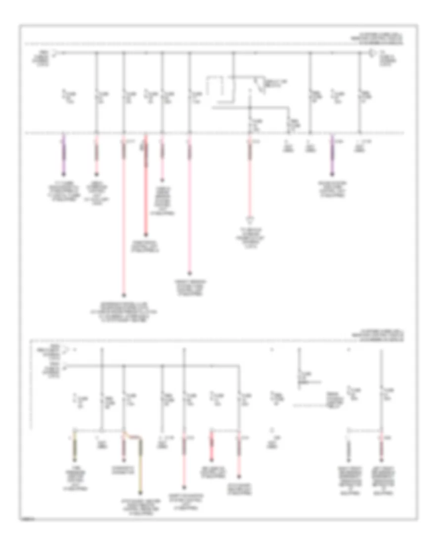
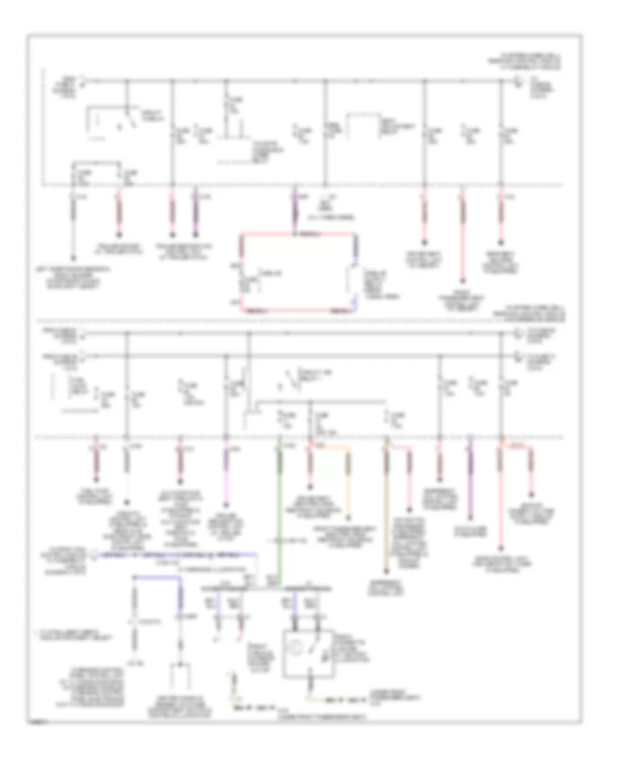
Электросхема блока предохранителей и реле, Купе (2 из 5) для Mercedes-Benz E350 2012
Электросхема блока предохранителей и реле, Купе (2 из 5) для Mercedes-Benz E350 2012 - Список элементов:
- (diagram 1 of 5)
- (in spare wheelwell) rear sam control module w/ fuse/relay module
- (not used)
- (or pnk/red)
- 13a
- C11t
- C12i
- C13a
- C14i
- C15h
- C3i
- C88
- C89
- Circuit 15 relay
- Circuit 15r relay (1)
- Driver seat neck-pro head restraint solenoid
- Emergency call system control unit (if equipped)
- From fuse 46 c (diagram 1 0f 5)
- From fuse 52 (diagram g 2 0f 5)
- From fuse 61 b
- From fuse 76 (diagram 3 0f 5)
- Front bumper left distronic sensor (w/ video & radar sensor system control unit), front bumper right distronic sensor (w/ video & radar sensor system control unit), front bumper left inner radar sensor (w/ city assist system), left rear bumper intelligent radar sensor (w/ blind spot assist) & right rear bumper inteligent radar sensor (w/ blind spot assist)
- Front cigarette lighter w/ ashtray illumination (w/ smoker package)
- Front passenger seat neck-pro head restraint solenoid
- Front vehicle interior power outlet (w/ o smoker package)
- Fuel pump control unit
- Fuel pump relay
- Fuse 15a
- Fuse 20a
- Fuse 25a
- Fuse 30a
- Fuse 5a
- Fuse 7.5a
- Left front seat ventilation blower regulator (if equipped) & right front seat ventilation blower regulator (if equipped)
- Multicontour seat pneumatic pump (if equipped)
- Nca
- Overhead control panel electronics
- Rear control unit
- Red
- Res fuse
- Seat adjustment relay
- To driver side sam control module w/ fuse & relay module (diagram 4 of 5)
- To fuse 42 (diagram 2 of 5)
- To fuse 73 (diagram 3 0f 5)
- To fuse 85 (diagram 3 0f 5)
- Trailer recognition control unit (w/ trailer hitch)
- Trailer socket
- Vehicle interior power outlet (w/ rear socket)
- W/ smoker package
- W/o smoker package
- W19 (under front passenger seat)
- X18/37
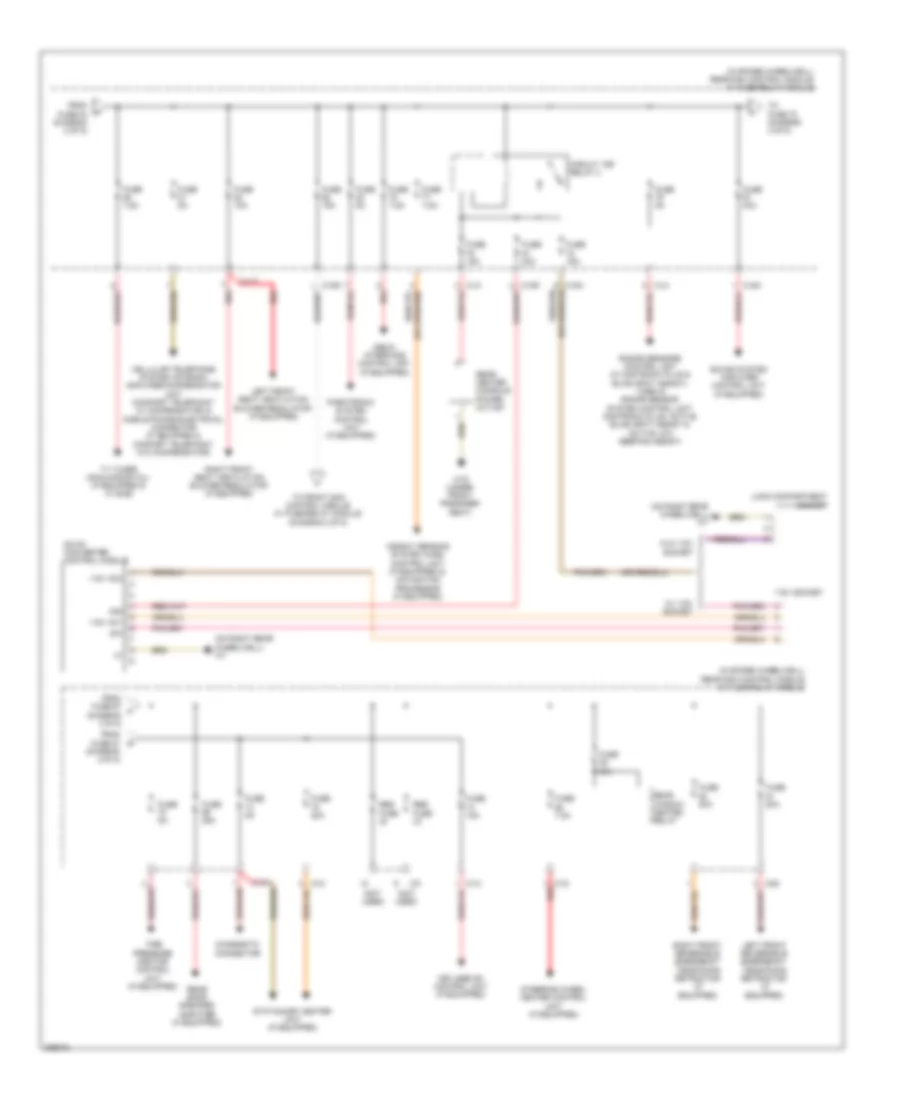
Электросхема блока предохранителей и реле, Купе (3 из 5) для Mercedes-Benz E350 2012
Электросхема блока предохранителей и реле, Купе (3 из 5) для Mercedes-Benz E350 2012 - Список элементов:
- (in spare wheelwell) rear sam control module w/ fuse/relay module
- (not used)
- (or pnk/red) red
- Adaptive damping system control unit (if equipped)
- C11r
- C11t
- C12i
- C14i
- C15h
- C2g
- C90
- Circuit 15r relay(2)
- Compensator/cellular telephone system umts (w/ mobile phone preinstallation w/ universal interface & w/ stationary heater)
- Diagnostic connector
- From fuse 60 (diagram 2 of 5)
- From fuse 84 (diagram 2 0f 5)
- From res fuse 91 j (diagram 3 0f 5)
- Fuse 15a
- Fuse 20a
- Fuse 25a
- Fuse 30a
- Fuse 40a
- Fuse 50a
- Fuse 5a
- Fuse 7.5a
- Keyless go control unit (if equipped)
- Left front reversible emergency tensioning retractor (if equipped)
- Media interface control unit (w/ auxiliary jack)
- Parktronic control unit (if equipped) &
- Rear window heated relay
- Red
- Res fuse
- Right front reversible emergency tensioning retractor (if equipped)
- Sound system amplifier control unit (if equipped)
- Stationary heater radio remote control receiver (if equipped)
- Stationary heater unit (if equipped)
- Tire pressure monitor control unit (if equipped)
- To fuse 70 (diagram 3 of 5)
- To vehicle interior power outlet (daigram 2 of 5)
- Tv tuner (analog/digital) (if equipped) & tv digital tuner (if equipped)
- Video & radar sensor system control unit (if equipped)
- Weight sensing system (wss) control unit (if equipped)
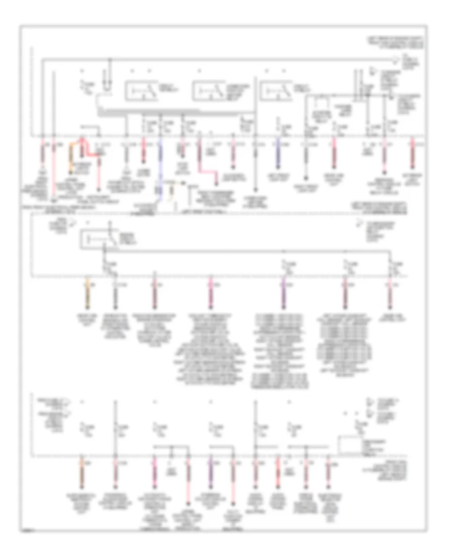
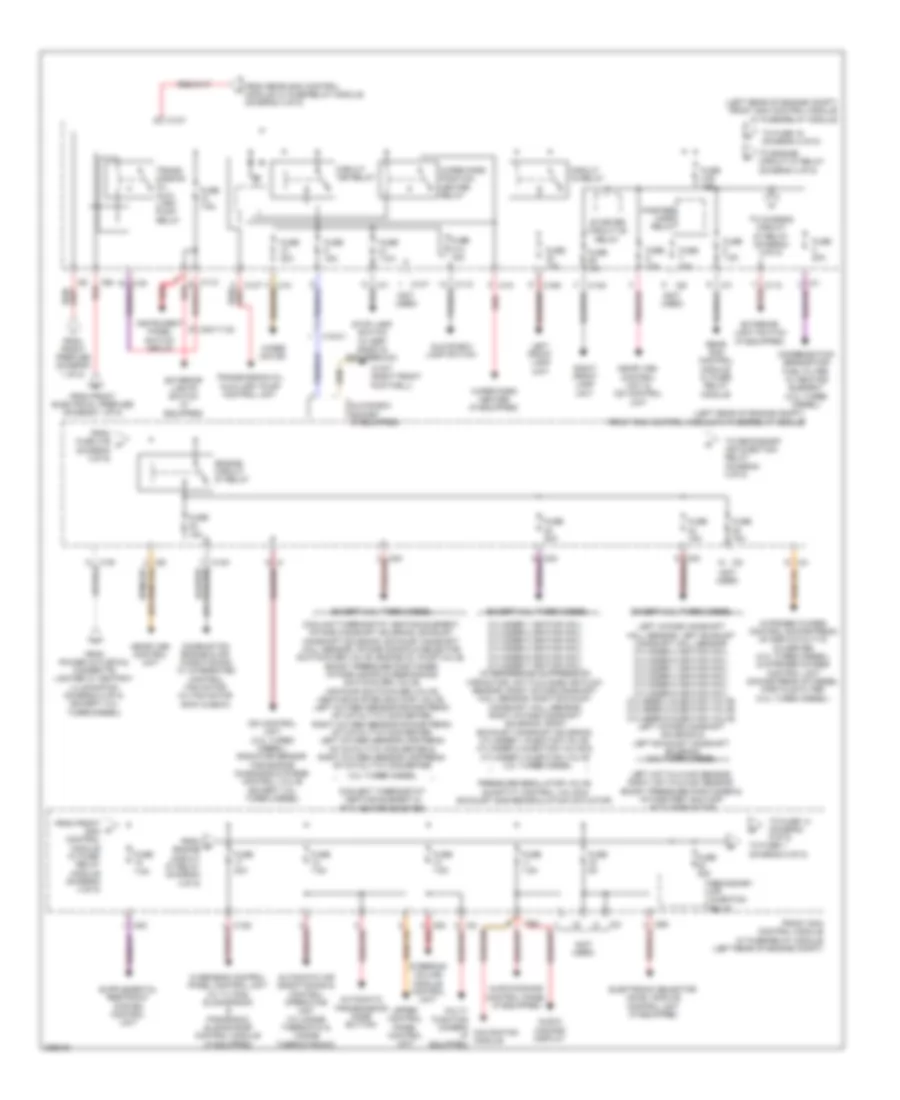
Электросхема блока предохранителей и реле, Купе (4 из 5) для Mercedes-Benz E350 2012
Электросхема блока предохранителей и реле, Купе (4 из 5) для Mercedes-Benz E350 2012 - Список элементов:
- (diagram 4 0f 5)
- (left front footwell)
- (left rear of engine compt) front sam control module w/ fuse/relay module
- (not used)
- 16s red
- Audio/ comand control panel
- Audio/ comand display (if equipped)
- Automatic air conditioning control & operating unit (w/ 2-zone thermatic & 3-zone thermotronic)
- C10t
- C11c
- C13d
- C14m
- C15m
- C19i
- C1m
- C2i
- C3m
- C4i
- C5c
- C6i
- C7i
- C9g
- Circuit 15 relay
- Circuit 15r relay
- Combustion engine & air conditioning w/ integrated control fan motor
- Coolant thermostat heating element, intake manifold resonance flap switchover valve, intake manifold switchover valve, air pump switchover valve, heating system shutoff valve, left oxygen sensor down stream of catalytic converter, right oxygen sensor down stream of catalytic converter, left oxygen sensor up stream of catalytic converter & right oxygen sensor up stream of catalytic converter
- Cylinder 1 ignition coil, cylinder 2 ignition coil, cylinder 3 ignition coil, radio interference suppression capacitor 1, hot film maf sensor, right intake camshaft hall sensor, right exhaust camshaft hall sensor, right intake camshaft solenoid, right exhaust camshaft solenoid, cylinder 1 injection valve, cylinder 2 injection valve, cylinder 3 injection valve & pressure regulator valve
- Electronic selector level module control unit (a/t)
- Engine circuit 87 relay
- Exterior light switch
- Exterior lights switch
- Fanfare horn relay
- From engine o circuit 87 relay (diagram 4 0f 5)
- From front electrical prefuse box (diagram 1 of 5)
- From fuse 18 (diagram m 4 0f 5)
- From fuse 31b n
- From power outlets & cigarette lighter (diagram 2 of 5)
- Front passenger seat occupied recognition & acsr (if equipped)
- Front sam control module w/ fuse/relay module (left rear of engine compt)
- Fuse 10a
- Fuse 15a
- Fuse 20a
- Fuse 30a
- Fuse 31a 15a
- Fuse 31b 15a
- Fuse 40a
- Fuse 5a
- Fuse 7.5a
- Glove box lamp switch
- Glove box socket (if equipped)
- Instrument panel switch group
- Left front lamp unit
- Left intake camshaft hall sensor, left exhaust camshaft hall sensor, cylinder 4 ignition coil, cylinder 5 ignition coil, cylinder 6 ignition coil, radio interference suppression capacitor 2, cylinder 4 injection valve, cylinder 5 injection valve, cylinder 6 injection valve, left intake camshaft solenoid & left exhaust camshaft solenoid
- Me-sfi (me) control unit
- Mobile phone electrical connector (if equipped)
- Multi- function camera (if equipped)
- Nca
- Panoramic sliding roof control module (if equipped)
- Pnk/
- Pnk/red
- Radiator sensor for engine diagnosis (w/ sulev), activated charcoal filter shutoff valve & purge control valve
- Rear sam control module w/ fuse/ relay module
- Red
- Right front lamp unit
- Secondary air injection relay
- Starter circuit 50 relay
- Steering column module control unit
- Stop lamp switch
- To chassis circuit 87 relay (diagram 5 0f 5)
- To engine circuit 87 relay (diagram 4 0f 5)
- To fuse 1 (diagram 5 0f 5)
- To fuse 14 (diagram 5 0f 5)
- To fuse 15 (diagram 4 0f 5)
- To secondary air injection relay (diagram 4 0f 5)
- Upper control panel control unit (early production)
- Upper control panel control unit (late production)
- W15/5
- Wiper motor
- Wiper park heater (if equipped)
- Wiper park position heater relay
- X18-c2
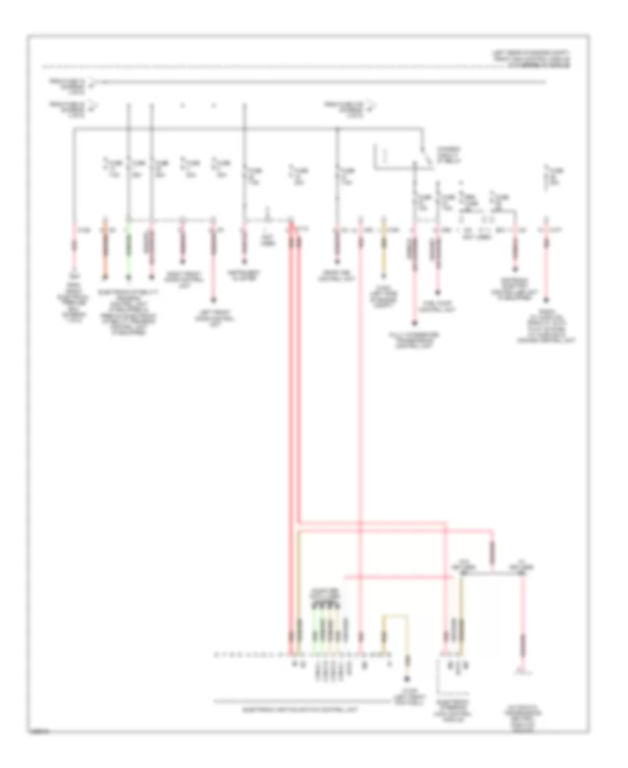
Электросхема блока предохранителей и реле, Купе (5 из 5) для Mercedes-Benz E350 2012
Электросхема блока предохранителей и реле, Купе (5 из 5) для Mercedes-Benz E350 2012 - Список элементов:
- (left rear of engine compt) front sam control module w/ fuse/relay module
- (not used)
- 30z
- Automatic transmission neutral position switch
- C10t
- C11c
- C12s
- C15m
- C2i
- C4i
- C5c
- C7i
- C9g
- Can-b h
- Can-b l
- Can-e h
- Can-e l
- Chassis circuit 87 relay
- Computer data lines system
- Data
- Distronic electric controller unit (if equipped)
- Electronic ignition switch control unit
- Electronic stability program control unit (if equipped) & premium electronic stability program control unit (if equipped)
- Electronic steering lock control module
- From front electrical prefuse box (diagram 1 of 5)
- From fuse 16 (diagram 4 of 5)
- From fuse 31b (diagram 4 of 5)
- From fuse 32 (diagram 4 of 5)
- Fuel pump control unit
- Fully integrated transmission control unit
- Fuse 10a
- Fuse 20a
- Fuse 25a
- Fuse 30a
- Fuse 50a
- Fuse 5a
- Fuse 7.5a
- Instrument cluster
- Left front door control unit
- Me-sfi (me) control unit
- Radio (w/ audio 20), radio w/ auto pilot system (w/ audio 50) & comand control unit
- Red
- Res fuse
- Right front door control unit
- W/ keyless go
- W/o keyless go
- W15/5 (left front footwell)
- W16/3 (left side of engine compt)
Электросхема блока предохранителей и реле, седан (1 из 5) для Mercedes-Benz E350 2012
Электросхема блока предохранителей и реле, седан (1 из 5) для Mercedes-Benz E350 2012 - Список элементов:
- (not used)
- (or nca)
- (right rear of engine compt) front electrical prefuse box
- A/c housing (w/ 2-zone thermatic & 3-zone thermotronic)
- Airmatic relay (if equipped & w/ electronic level conrtol w/ hydraulics)
- Alarm siren (if equipped)
- Alternator
- Battery sensor
- C12i
- C1v
- C2v
- C3i
- C8d
- C9i
- Cc1
- Combustion engine & air conditioning w/ integrated control fan motor (w/ fan motor 800w & 650w)
- Coolant circulation pump relay
- Electrical power steering control unit (if equipped)
- From fuse 155 (diagram 1 of 5)
- From rear prefuse (diagram 1 of 5)
- Front electrical prefuse box (right rear of engine compt)
- Fuse
- Fuse 100a
- Fuse 150a
- Fuse 15a
- Fuse 30a
- Fuse 400a
- Fuse 40a
- Fuse 50a
- Fuse 60a
- Fuse 7.5a
- Glow output stage (3.0l turbo diesel)
- Ig1
- Im1
- Intelligent servo module for direct select (if equipped)
- Interference suppression capacitor
- Interior protection & tow-away protection control unit
- Ism
- Left rear door control unit
- Mr1
- Mr2
- Mr4
- Mr5
- Mr6
- Mr7
- Mr8
- Mrg2
- On-board electrical system battery
- Ptc heater booster (if equipped, w/ 2-zone thermatic & 3-zone thermotronic)
- Quiescent current cutout relay
- Rear blower motor (w/ 3-zone thermotronic)
- Rear on-board electrical system battery
- Rear prefuse
- Rear sam control module w/ fuse/ relay module (in spare wheelwell)
- Rear window antenna amplifier 1, fm 1, am, cl (zv) & keyless go antenna amplifier
- Red
- Right rear door control unit
- Starter
- Starting/charging system
- Terminal block (circuit 30)
- To circuit 15 relay (diagram 2 of 5)
- To front sam control module w/ fuse/ relay module (diagram 4 of 5)
- To front sam control module w/ fuse/relay module (diagram 4 of 5)
- To front sam control module w/ fuse/relay module (diagram 5 of 5)
- To fuse 157 (diagram 1 of 5)
- To fuse 42 (diagram 2 of 5)
- To rear sam control module w/ fuse/ relay module (diagram 1 of 5)
- Trunk lid control unit (if equipped)
- W/ front battery
- W/ rear battery
- W/o front battery
- W16/4 (right side of engine compt)
Электросхема блока предохранителей и реле, седан (2 из 5) для Mercedes-Benz E350 2012
Электросхема блока предохранителей и реле, седан (2 из 5) для Mercedes-Benz E350 2012 - Список элементов:
- (diagram 1 of 5)
- (in spare wheelwell) rear sam control module w/ fuse/relay module
- (not used)
- (under front passenger's seat) w19
- 22a
- 3.0l turbo diesel
- Aag
- Airmatic control unit (if equipped) & rear axle electronic level contrl unit (if equipped)
- C11t
- C12i
- C13a
- C15h
- C3i
- Center console armrest stowage compartment switch & controls illumination
- Circuit 15 relay
- Circuit 15r relay 1
- Driver seat control unit (w/ memory)
- Driver seat neck-pro head restraint solenoid (if equipped)
- Dvd player (if equipped)
- E22
- Emergency call system control unit
- Emergency call system control unit (if equipped)
- From fuse 46 c (diagram 1 0f 5)
- From fuse 61 b
- From fuse 63 (diagram g 2 0f 5)
- Front cigarette lighter w/ ashtray illumination
- Front passenger seat control unit (w/ memory)
- Front passenger seat neck-pro head restraint solenoid (if equipped)
- Front vehicle interior power outlet
- Fuel pump control unit (if equipped)
- Fuel pump relay
- Fuse 15a
- Fuse 20a
- Fuse 25a
- Fuse 30a
- Fuse 5a
- Fuse 5a (or 7.5a)
- Fuse 7.5a
- Fuse 7.5a (or 30a)
- Left inner radar sensor & front bumper (w/distronic plus & blind spot assist)
- Module for direct select
- Multicontour seat pneumatic pump (if equipped) & dynamic multicontour seat pneumatic pump (if equipped)
- Navigation processor (if equipped), emergency call system control unit (if equipped) & backup camera
- Nca
- Overhead control panel control unit (w/ tilting/sliding roof) (in overhead console) overhead control panel electronics (w/o tilting/sliding roof)
- Rear seat heaters control unit (if equipped)
- Red
- Res fuse
- Scr
- Sdar control unit/ high definition tuner (if equipped)
- Seat adjustment relay
- Tailgate windshield wiper relay
- To front sam control module w/ fuse/relay module (diagram 4 of 5)
- To fuse 68 (diagram 2 of 5)
- To fuse 73 (diagram 3 0f 5)
- To fuse 85 (diagram 3 0f 5)
- Trailer recognition control unit (w/ trailer hitch)
- Trailer socket (w/ trailer hitch)
- W/ ambiance illumination
- W/ intelligent servo
- W/ smoker package
- W/o smoker package
- W19 (under front passenger's seat)
- X138/1-c2
- X18/37-c1
- X29/5
Электросхема блока предохранителей и реле, седан (3 из 5) для Mercedes-Benz E350 2012
Электросхема блока предохранителей и реле, седан (3 из 5) для Mercedes-Benz E350 2012 - Список элементов:
- (in spare wheelwell) rear sam control module w/ fuse/relay module
- (not used)
- (on right rear wheelwell) w7
- 115v ac1
- 115v ac2
- 115v socket
- 30g
- C10r
- C11t
- C12i
- C14i
- C15h
- C2g
- C3i
- Cellular telephone system antenna amplifier/compensator unit (comfort telephony w/ compensator) & mobile phone electrical connector (if equipped & confort telephony w/o compensator)
- Circuit 15r relay 2
- Dc/ac converter control module
- Diagnostic connector
- From fuse 67 j (diagram 3 0f 5)
- From fuse 84 (diagram 2 of 5)
- From fuse 87 (diagram 2 0f 5)
- Fuse 10a
- Fuse 15a
- Fuse 20a
- Fuse 25a
- Fuse 30a
- Fuse 40a
- Fuse 50a
- Fuse 5a
- Fuse 7.5a
- Keyless go control unit (if equipped)
- Left front reversible emergency tensioning retractor (if equipped)
- Left front seat ventilation blower regulator (if equipped)
- Load compartment socket
- Media interface control unit (if equipped)
- Parktronic system control unit (if equipped)
- Radar sensors control unit (w/ distronic plus & blind spot assist), video & radar sensor system control unit (distronic plus, active blind spot assist & active low keeping assist)
- Rear bass speaker amplifier (if equipped)
- Rear center console power outlet
- Rear window heated relay
- Red
- Res fuse
- Right front reversible emergency tensioning retractor (if equipped)
- Right front seat ventilation blower regulator (if equipped)
- Sound system amplifier control unit (if equipped)
- Stationary heater unit (if equipped)
- Steering wheel heater control unit (if equipped)
- Tire pressure monitor control unit (if equipped)
- To front sam control module w/ fuse/relay module (diagram 4 of 5)
- To fuse 70 (diagram 3 of 5)
- Tv tuner (analog/digital) (if equipped & w/ ece)
- W/ 115v socket
- W/o 115v socket
- W19 (under front passnger seat)
- Weight sensing system (wss) control unit (if equipped) & navigation processor (if equipped)
Электросхема блока предохранителей и реле, седан (4 из 5) для Mercedes-Benz E350 2012
Электросхема блока предохранителей и реле, седан (4 из 5) для Mercedes-Benz E350 2012 - Список элементов:
- (diagram 4 0f 5)
- (left rear of engine compt) front sam control module w/ fuse/relay module
- (not used)
- 16s
- 3.0l turbo diesel
- Audio/ comand display
- Audio/comand control panel (if equipped)
- Automatic air conditioning & control operating unit (w/ 2-zone thermatic & 3-zone thermotronic)
- Automatic transmission mode button
- C10t
- C11c
- C13d
- C14m
- C15m
- C19i
- C1m
- C2i
- C3m
- C4i
- C5c
- C6i
- C7i
- C9g
- Cdi control unit (3.0l turbo diesel), radiator sensor for engine diagnosis & purge control valve (except 3.0l turbo diesel)
- Circuit 15 relay
- Circuit 15r relay
- Combustion engine & air conditioning w/ integrated control fan motor (w/ fan motor 800w & 650w)
- Condensation sensor for fuel filter w/ heating element (3.0l turbo diesel)
- Coolant thermostat heating element, intake camshaft solenoid, exhaust camshaft solenoid, exhaust camshaft hall sensor, intake manifold selector switchover valve, engine oil pump valve, boost pressure positioner, intake manifold resonance switchover valve, air pump switchover valve, heating system shutoff valve, left oxygen sensor downstream of catalytic converter, right oxygen sensor downstream of catalytic converter, left oxygen sensor upstream of catalytic converter & right oxygen sensor upstream of catalytic converter
- Coolent thermostat heating element & ptc heater booster
- Cylinder 1 ignition coil, cylinder 2 ignition coil, cylinder 3 ignition coil, cylinder 4 ignition coil, cylinder 6 ignition coil, cylinder 7 ignition coil, interference suppression capacitor, hot film mass air flow sensor, right intake camshaft hall sensor, right exhaust camshaft hall sensor, right intake camshaft solenoid, right exhaust camshaft solenoid, cylinder 1 injection valve, cylinder 2 injection valve & cylinder 3 injection valve
- Electronic selector level module control unit (if equipped)
- Engine circuit 87 relay
- Except 3.0l turbo diesel
- Exterior light switch (if equipped)
- Exterior lights switch (if equipped)
- Fanfare horn relay
- From front electrical prefuse (diagram 1 of 5)
- From front prefuse (diagram 1 of 5)
- From front sam control module w/ fuse/ relay module (diagram 4 of 5)
- From fuse 31b n
- From o engine circuit 87 relay (diagram 4 0f 5)
- From power outlets & cigarette lighter w/ ashtray illumination (diagram 2 of 5) (except 3.0l turbo diesel)
- From rear sam control module w/ fuse/relay module (diagram 3 0f 5)
- Front sam control module w/ fuse/relay module (left rear of engine compt)
- Fuse 10a
- Fuse 15a
- Fuse 20a
- Fuse 30a
- Fuse 31a 15a
- Fuse 31b 15a
- Fuse 40a
- Fuse 5a
- Fuse 7.5a
- Glove box lamp switch
- Glove box socket (if equipped)
- Instrument panel switch group
- Left front lamp unit
- Left hot film maf sensor, right hot film maf sensor, boost pressure positioner & intake port shutoff actuator motor
- Left intake camshaft hall sensor, left exhaust camshaft hall sensor, cylinder 4 ignition coil, cylinder 5 ignition coil, cylinder 1 ignition coil, cylinder 3 ignition coil, cylinder 8 ignition coil, cylinder 6 ignition coil, cylinder 4 injection valve, cylinder 5 injection valve, cylinder 6 injection valve, left intake camshaft solenoid & left exhaust camshaft solenoid 3.0l turbo diesel
- Me-sfi (me) control unit
- Me-sfi (me) control unit & cdi control unit
- Multi- function camera navigation (if module equipped)
- Nitrogen oxides control downstream of scr catalytic coverter (3.0l turbo diesel) & nitrogen oxides control unit downstream of diesel particle filter (3.0l turbo diesel)
- Overhead control panel control unit (w/ tilting/ sliding roof) & panoramic sliding roof control module (if equipped)
- Pnk/red
- Pressure regulator valve, quantity control valve & exhaust gas recirculation actuator
- Rear sam control module w/ fuse/ relay module
- Red
- Right front lamp unit
- Secondary air injection relay
- Starter circuit 50 relay
- Steering column module control unit
- Stop lamp switch (w/ esp basic & esp premium)
- To chassis circuit 87 relay (diagram 5 0f 5)
- To engine circuit 87 relay (diagram 4 0f 5)
- To fuse 1 (diagram 5 0f 5)
- To fuse 14 (diagram 5 0f 5)
- To fuse 15 (diagram 4 0f 5)
- To secondary air injection relay (diagram 4 0f 5)
- Trans- mission oil auxi- liary pump relay
- Transmission oil auxiliary pump control unit
- Upper control panel control unit
- W15/7 (right front footwell)
- Wiper motor
- Wiper park heater (if equipped)
- Wiper park position heater relay
- X18-c1
- X83/11-c2
Электросхема блока предохранителей и реле, седан (5 из 5) для Mercedes-Benz E350 2012
Электросхема блока предохранителей и реле, седан (5 из 5) для Mercedes-Benz E350 2012 - Список элементов:
- (left rear of engine compt) front sam control module w/ fuse/relay module
- (not used)
- 30z
- Additional battery
- Automatic transmission neutral position switch
- C10t
- C11c
- C12s
- C15m
- C17c
- C2i
- C4i
- C5c
- C7i
- C9g
- Can-b h
- Can-b l
- Can-e h
- Can-e l
- Cdi control unit (3.0l turbo diesel)
- Chassis circuit 87 relay
- Computer data lines system
- Data
- Distronic electric controller unit
- Electronic ignition switch control unit
- Electronic stability program control unit (if equipped) & premium electronic stability program control unit (if equipped)
- Electronic steering lock control module
- Electronic transmission control control unit (if equipped)
- Ezs backup
- From front electrical prefuse box (diagram 1 of 5)
- From fuse 16 (diagram 4 of 5)
- From fuse 31b u (diagram 4 of 5)
- From fuse 32 (diagram 4 of 5)
- From rear prefuse (diagram 1 of 5)
- Front sam control module w/ fuse/relay module
- Fuel pump control unit
- Fully integrated transmission control unit
- Fuse
- Fuse 10a
- Fuse 20a
- Fuse 25a
- Fuse 30a
- Fuse 40a
- Fuse 5a
- Fuse 7.5a
- Fuse box
- Instrument cluster
- Left front door control unit
- Me-sfi (me) control unit (except 3.0l turbo diesel) &
- Module for direct select
- Night vision assist control unit
- P not
- Radio (w/ audio 20), radio w/ auto pilot system (w/ audio 50) & comand control unit (if equipped)
- Red
- Right front door control unit
- W/ direct select
- W/ front battery
- W/ intelligent servo
- W/ keyless go
- W/ rear battery
- W/o direct select
- W/o intelligent servo
- W/o keyless go
- W15/5 (left front footwell)
- X190-c1