БЛОК ПРЕДОХРАНИТЕЛЕЙ И РЕЛЕ
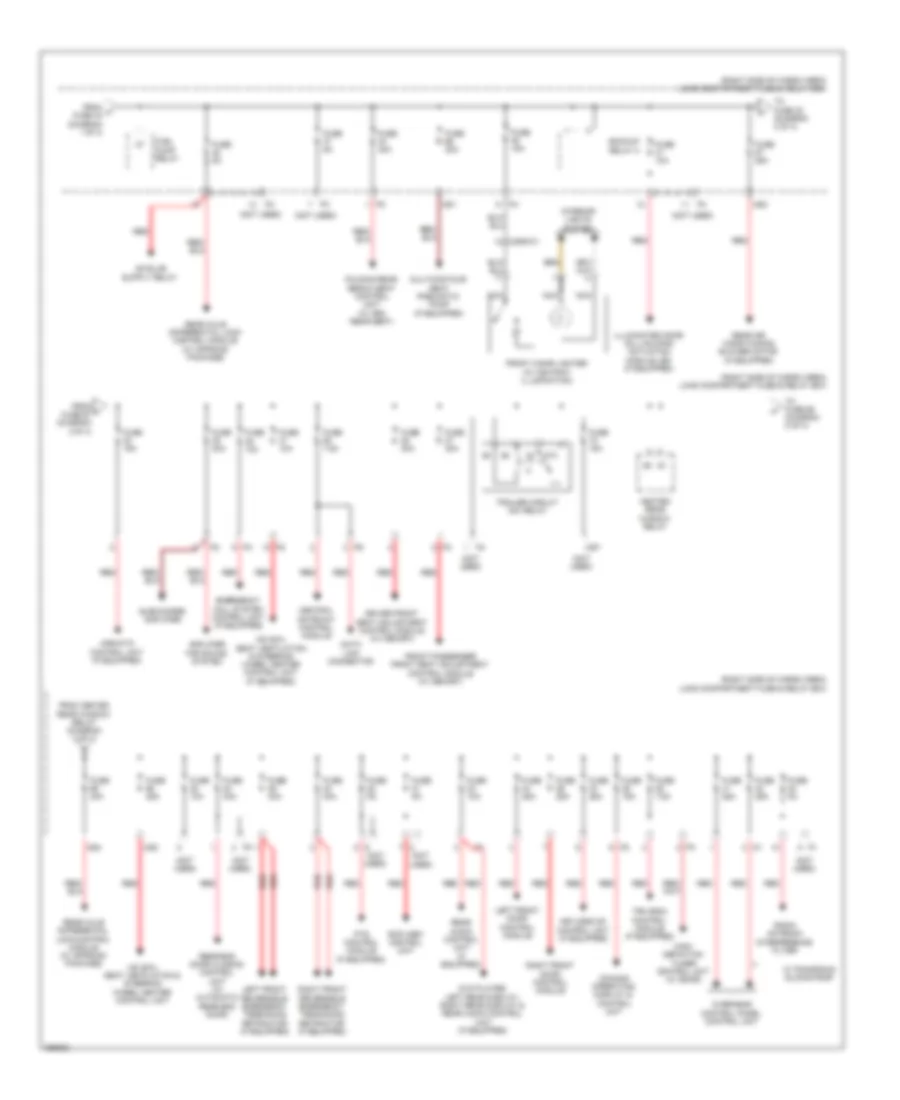
Электросхема блока предохранителей и реле (1 из 4) для Mercedes-Benz GL350 2012

Электросхема блока предохранителей и реле (1 из 4) для Mercedes-Benz GL350 2012 - Список элементов:
- (not used)
- (right rear of cargo area) load compartment fuse & relay box
- 87a
- Ac air recirculation unit
- Activated charcoal filter shutoff valve
- Backup
- Battery
- Battery compartment prefuse box (behind right front seat)
- C78
- C79
- C80
- C81 red
- C82
- C83
- C84
- C85
- C86
- C88
- C89
- C90
- C91
- Camera (if equipped)
- Circuit 15r 2/ spare 1 relay (change over contact)
- Circuit 15r relay
- Circuit 31 right wheel house luggage compartment voltage distributor connector
- Circuit relay/spare 1 relay (change over contact)
- Driver lumbar support regulator control unit (if equipped)
- Driver neck- pro head restraint solenoid (w/ crash active head restraints)
- Driver seat adjustment switch (if equipped)
- Emergency call system control unit (if equipped)
- Front interior socket
- Front passenger lumbar support regulator control unit (if equipped)
- Front passenger neck-pro head restraint solenoid (w/ crash active head restraints)
- Front passenger seat adjustment switch (if equipped)
- Front sam control unit
- Fuse 100a
- Fuse 10a
- Fuse 150a
- Fuse 15a
- Fuse 20a
- Fuse 30a
- Fuse 40a
- Fuse 5a
- Fuse 60a
- Fuse 7.5a
- Fuse 70a
- Glove compartment illumination w/ switch
- Instrument cluster & rotary light switch
- Left rear bumper intelligent radar sensor & right rear bumper intelligent radar sensor
- Load compartment socket
- Multicontour seat pneumatic pump (if equipped)
- Pnk
- Ptc heater booster (if equipped)
- Pyrotechnical separator
- Rear sam control module
- Rear sam control module & front sam control module
- Rear wiper relay
- Red
- Restraint systems control module
- Right 2nd seat row socket
- Socket circuit 15r relay (w/ run-on)
- Spare 2 relay (normally open contact)
- Tailgate wiper motor
- To 115v socket (diagram 3 of 4)
- To cockpit fuse box (diagram 4 of 4)
- To dc/ac converter control unit (115v socket) (diagram 3 of 4)
- To engine compartment fuse & relay box (diagram 3 of 4)
- To front prefuse (diagram 3 of 4)
- To fuse (diagram 3 of 4)
- To fuse pump relay (diagram 2 of 4)
- Trailer circuit 30 relay
- Transfer case control unit (w/ offroad package)
- W15/1 (right front footwell)
- W29/2 (behind right kick panel)
- W6/6 (left rear of cargo area floor)
- W7 (at right "d" pillar)
- Wss control unit (weight sensing system)
- X18-c2
- X25/2-c2 d4
- X25/2-c2 h2
- X29/6-c1
- X2916-c1
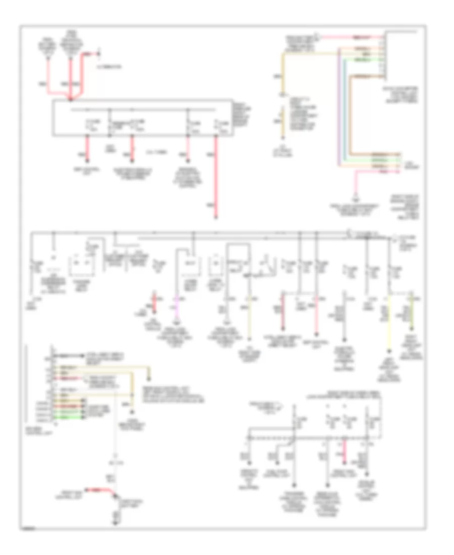
Электросхема блока предохранителей и реле (2 из 4) для Mercedes-Benz GL350 2012
Электросхема блока предохранителей и реле (2 из 4) для Mercedes-Benz GL350 2012 - Список элементов:
- (not used)
- (right side of cargo area) load compartment fuse & relay box
- 87a
- Airmatic control unit (if equipped)
- Amplifier for sound system
- Backup relay 2
- Central gateway control module
- Comand operating, display & control unit
- Data link connector
- Driver front seat adjustment control module (w/ memory)
- Dvd player, left rear display, right rear display & rear audio control unit (if equipped)
- Emergency call system control unit (if equipped)
- Folding rear bench seat control unit (w/ 3rd rear seat)
- From h fuse 43 (diagram 1 0f 4)
- From heated rear window relay (diagram 2 of 4)
- From j fuse 67 (diagram 2 0f 4)
- Front cigar lighter (w/ ashtray illumination)
- Front passenger front seat adjustment control module (w/ memory)
- Fuel pump relay
- Fuse 10a
- Fuse 15a
- Fuse 25a
- Fuse 30a
- Fuse 40a
- Fuse 5a
- Fuse 7.5a
- Heated rear window relay
- High- definition tuner control unit (w/ sdar)
- Hs (sih), seat ventilation & steering wheel heater control unit
- Hs (sih), seat ventilation & steering wheel heater control unit (if equipped)
- Illuminated door sill molding actuation module led (if equipped)
- Interior lights system
- Keyless go control unit (if equipped)
- Left front door control module
- Left front reversible emergency tensioning retractor (if equipped)
- Ms1
- Ms2
- Ms3
- Ms4
- Ms7
- Multicontour seat pneumatic pump (if equipped)
- Nca
- Overhead control panel control unit
- Pts control module (if equipped)
- Radio antenna interference filter
- Rcp (hbf) control unit
- Rear air conditioning blower motor (if equipped)
- Rear audio control unit (if equipped)
- Rear axle differential lock control module (w/ offroad package)
- Rear-end door closing control unit (w/ automatic rear end door)
- Red
- Right front door control module
- Right front reversible emergency tensioning retractor (if equipped)
- Subwoofer amplifier
- To fuse 32 (diagram 2 of 4)
- To fuse 69 (diagram 2 of 4)
- Tpm (rdk) control module (if equipped)
- Trailer circuit 30x relay
- W/ panoramic sliding roof
- X29/6-c1
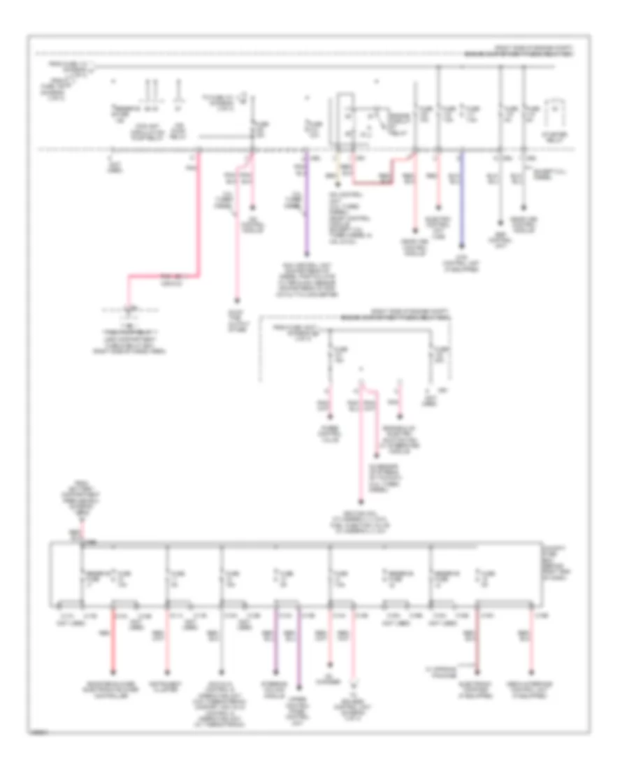
Электросхема блока предохранителей и реле (3 из 4) для Mercedes-Benz GL350 2012
Электросхема блока предохранителей и реле (3 из 4) для Mercedes-Benz GL350 2012 - Список элементов:
- (not used)
- (right side of cargo area) load compartment fuse & relay box
- (right side of engine compt) engine compartment fuse & relay box
- (w/ airmatic)
- 115v socket
- 3.0l turbo
- Additional battery
- Air suspension compressor relay
- Airmatic control unit (if equipped)
- Alternator
- C123
- C124
- C125
- Can-b h
- Can-b l
- Can-c h
- Can-c l
- Cdi control module
- Circuit
- Circuit 31 right wheelhouse luggage compartment voltage distributor connector
- Computer data lines system
- Dc/ac converter control unit (115v socket) (except hybrid)
- Eis (ezs) control unit
- Electro hydraulic power steering (if equipped)
- Electrohydraulic power steering (if equipped)
- Engine & ac electric suction fan w/ integrated control
- Esp control unit
- Fanfare horn relay
- From battery (diagram 1 of 4)
- From battery c compartment prefuse box (diagram 1 0f 4)
- From cockpit prefuse box (diagram 4 of 4)
- From fuse 51 (diagram r 1 of 4)
- From load compartment fuse & relay box (diagram 1 0f 4)
- From load compartment fuse & relay box (diagram 1 of 4)
- From pyro- technical separator (diagram 1 of 4)
- Front prefuse (right rear of engine compt)
- Front sam control unit
- Fuel pump control unit
- Fuse 100a
- Fuse 10a
- Fuse 15a
- Fuse 25a
- Fuse 30a
- Fuse 40a
- Fuse 5a
- Fuse 7.5a
- Intelligent servo module for direct select
- Ism
- Left front headlamp unit (w/ xenon headlamps)
- Mr1
- Mr3
- Mr4
- Pnk
- Rear axle differential lock control module (w/ offroad package)
- Rear sam control unit, left front door cl (zv) motor & illuminated door sill molding actuation module led
- Red
- Relay
- Reserve fuse
- Right front headlamp unit (w/ xenon headlamps)
- To fuse (diagram 4 of 4)
- To fuse 121 (diagram 4 of 4)
- Transfer case control module (w/ offroad package)
- W/ customer request option
- W/o customer request option
- W2 (right side of engine compt)
- W29/2 (behind right kick panel)
- W7 (at right "d" pillar)
- Wiper level 1/2 relay
- Wiper on/off relay
- X18
Электросхема блока предохранителей и реле (4 из 4) для Mercedes-Benz GL350 2012
Электросхема блока предохранителей и реле (4 из 4) для Mercedes-Benz GL350 2012 - Список элементов:
- (not used)
- (right side of engine compt) engine compartment fuse & relay box
- 3.0l turbo diesel
- Acc (kla) control & operating unit (w/o thermotronic) comfort acc (kla) control & operating unit (w/ thermotronic)
- Air pump relay
- Booster blower electronic blower controller
- C10a
- C10b
- C11a
- C11b
- C12a
- C12b
- C13a
- C13b
- C14a
- C14b
- C15a
- C15b
- C16a
- C16b
- C17a
- C17b
- C18a
- C18b
- C5e
- Cd changer
- Cdi control module
- Cdi control unit (3.0l turbo diesel) me-sfi control module (except 3.0l turbo diesel & 4.6l & 5.5l)
- Cockpit fuse box (behind right end of dash)
- Coolant circulation pump relay
- Dtr control unit (if equipped)
- Electric control unit (vgs)
- Electronic compass (if equipped)
- Engine & ac electric suction fan w/ integrated module
- Engine circuit relay
- Esp control unit
- Except 3.0l diesel
- From battery compartment prefuse box (diagram 1 of 4)
- From fuse 105 (diagram o 4 of 4)
- From fuse 112 (diagram m 3 of 4)
- From l fuse 109 (diagram 3 of 4)
- Fuel pump relay
- Fuse 10a
- Fuse 15a
- Fuse 20a
- Fuse 5a
- Fuse 7.5a
- Glow time output stage
- Ignition coil cylinders 2, 3, 5 & 8, fuel injection valve cylinder's 2, 3, & 8
- Instrument cluster
- Load compartment fuse & relay box (right side of cargo area)
- Me-sfi (me) control module
- Media interface control unit (if equipped)
- Mr1
- Mr2
- Mr3
- Mr4
- Nox control unit downstream of diesel particulate filter & nox sensor downstream of scr catalytic converter
- O2 sensor up stream of twc(kat) (3.0l turbo diesel)
- Pnk
- Purge control valve
- Red
- Reserve fuse
- Starter relay
- Steering column module
- To eis (ezs) control unit (diagram 3 of 4)
- To fuse 101 (diagram 4 of 4)
- Upper control panel control unit
- W/ offroad package
- X25/2-c2