БЛОК ПРЕДОХРАНИТЕЛЕЙ И РЕЛЕ
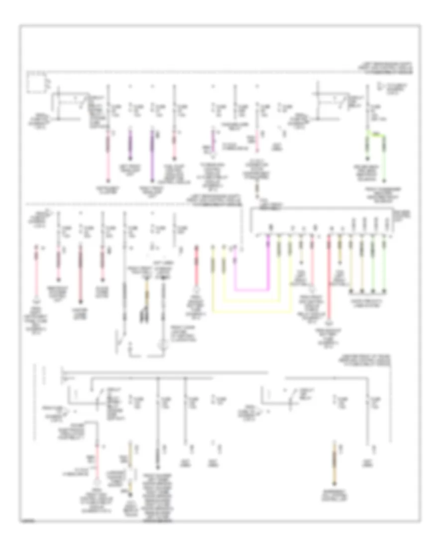
Электросхема блока предохранителей и реле (1 из 4) для Mercedes-Benz S550 4Matic 2012

Электросхема блока предохранителей и реле (1 из 4) для Mercedes-Benz S550 4Matic 2012 - Список элементов:
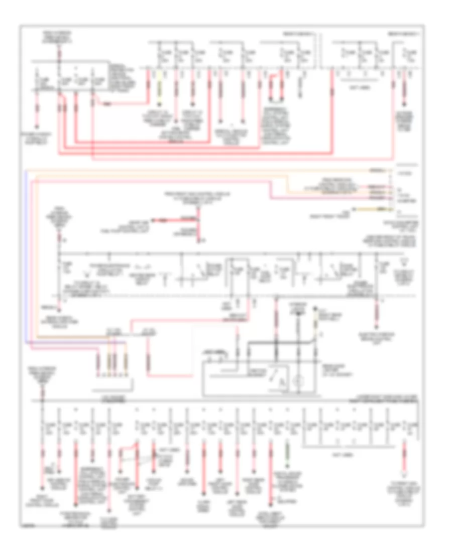
Электросхема блока предохранителей и реле (2 из 4) для Mercedes-Benz S550 4Matic 2012
Электросхема блока предохранителей и реле (2 из 4) для Mercedes-Benz S550 4Matic 2012 - Список элементов:
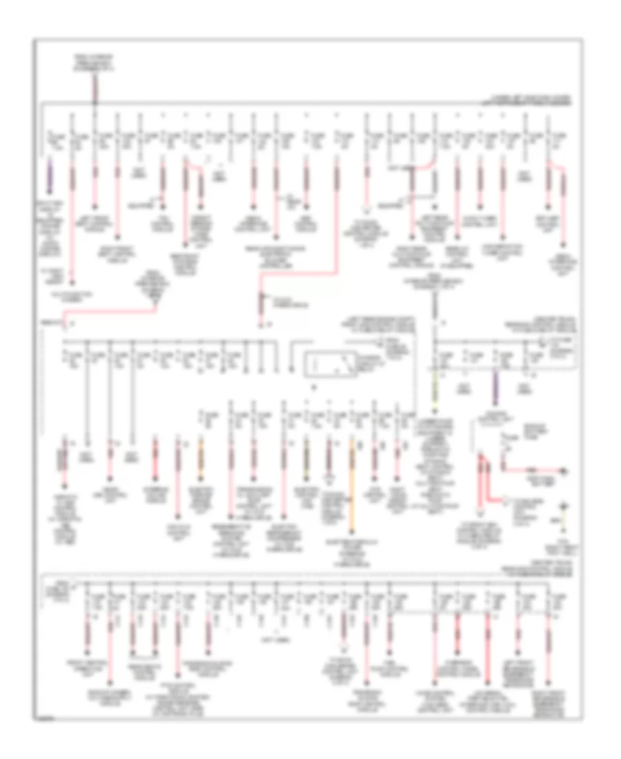
Электросхема блока предохранителей и реле (3 из 4) для Mercedes-Benz S550 4Matic 2012
Электросхема блока предохранителей и реле (3 из 4) для Mercedes-Benz S550 4Matic 2012 - Список элементов:
Электросхема блока предохранителей и реле (4 из 4) для Mercedes-Benz S550 4Matic 2012
Электросхема блока предохранителей и реле (4 из 4) для Mercedes-Benz S550 4Matic 2012 - Список элементов: