БЛОКИРОВКИ СЕЛЕКТОРА СТОЯНОЧНЫЙ ТОРМОЗ
электронная схема стояночного тормоза для Audi A6 3.2 2010

электронная схема стояночного тормоза для Audi A6 3.2 2010 - Список элементов:
- (on right rear caliper assembly) right parking brake motor
- (right side of
- 23a
- Computer data lines system
- Electro-mechanical
- Fuse 30a
- Fuse 5a
- Fuse holder
- Fuse panel sb
- Fuse panel sf
- G51 (on right rear wheelwell)
- Hot at all times
- Instrument cluster control module
- Interior lights system
- Left parking brake motor (on left rear caliper assembly)
- Luggage compt)
- Parking brake
- Parking brake pressure switch
- Power distribution system
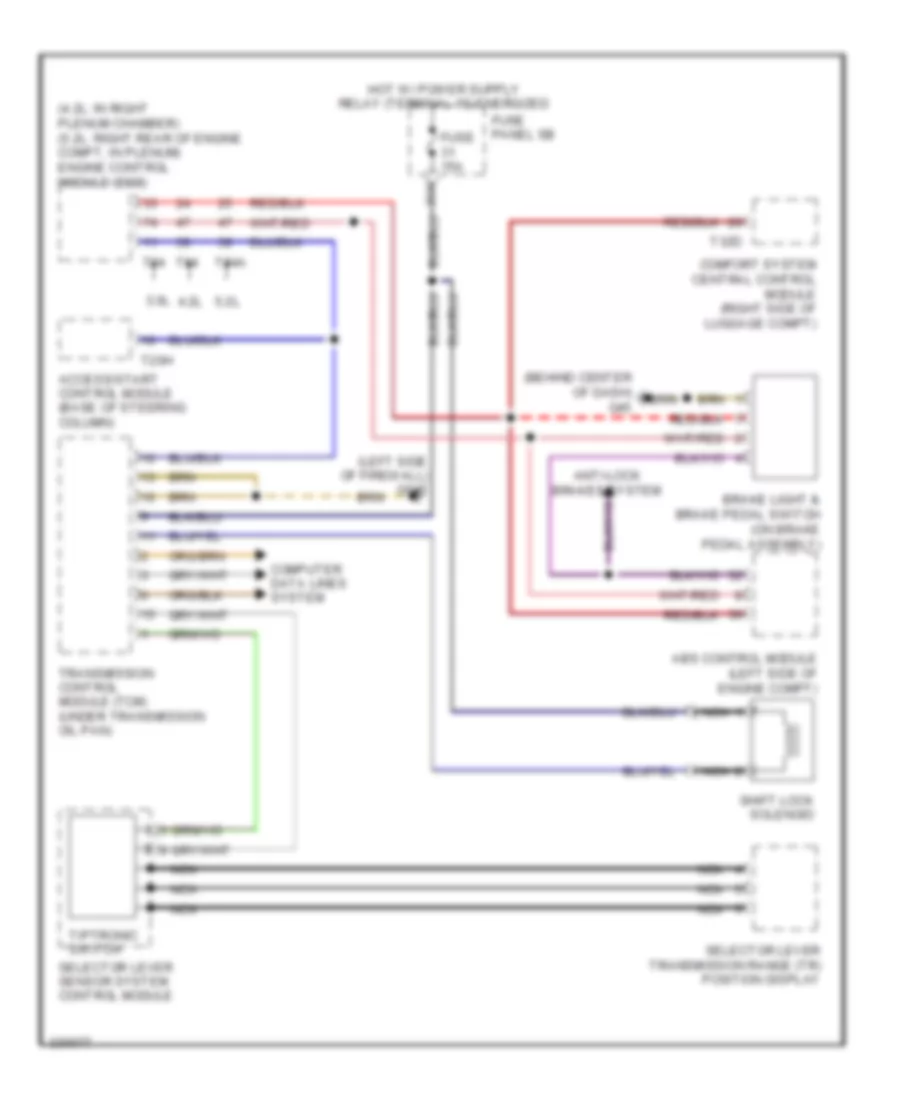
Электросхема блокировки селектора, 6 скоростей A/T для Audi A6 3.2 2010
Электросхема блокировки селектора, 6 скоростей A/T для Audi A6 3.2 2010 - Список элементов:
- (4.2l: in right plenum chamber) (5.2l: right rear of engine compt, in plenum) engine control module (ecm)
- (behind center of dash) g45
- (left side of firewall) g645
- 3.0l
- 31a
- 4.2l
- 5.2l
- Abs control module (left side of engine compt)
- Access/start control module (base of steering column)
- Anti-lock brakes system
- Brake light & brake pedal switch (on brake pedal assembly)
- Comfort system central control module (right side of luggage compt)
- Computer data lines system
- Fuse 15a
- Fuse panel sb
- Nca
- Selector lever sensor system control module
- Selector lever transmission range (tr) position display
- Shift lock solenoid
- T20h
- T32d
- T94
- T94a
- Tiptronic switch
- Transmission control module (tcm) (under transmission oil pan)
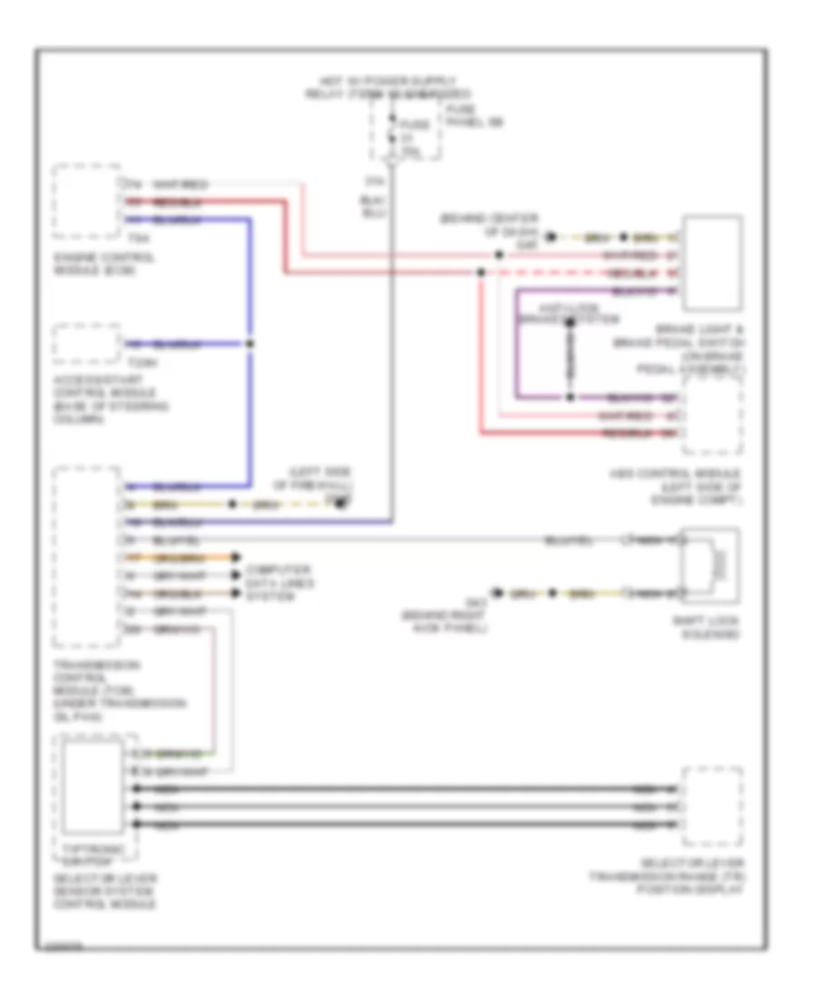
Электросхема блокировки селектора, CVT для Audi A6 3.2 2010
Электросхема блокировки селектора, CVT для Audi A6 3.2 2010 - Список элементов:
- (behind center of dash) g45
- (left side of firewall) g645
- 31a
- Abs control module (left side of engine compt)
- Access/start control module (base of steering column)
- Anti-lock brakes system
- Brake light & brake pedal switch (on brake pedal assembly)
- Computer data lines system
- Engine control module (ecm)
- Fuse 15a
- Fuse panel sb
- G43 (behind right kick panel)
- Nca
- Selector lever sensor system control module
- Selector lever transmission range (tr) position display
- Shift lock solenoid
- T20h
- T94
- Tiptronic switch
- Transmission control module (tcm) (under transmission oil pan)