БЛОКИРОВКИ СЕЛЕКТОРА СТОЯНОЧНЫЙ ТОРМОЗ
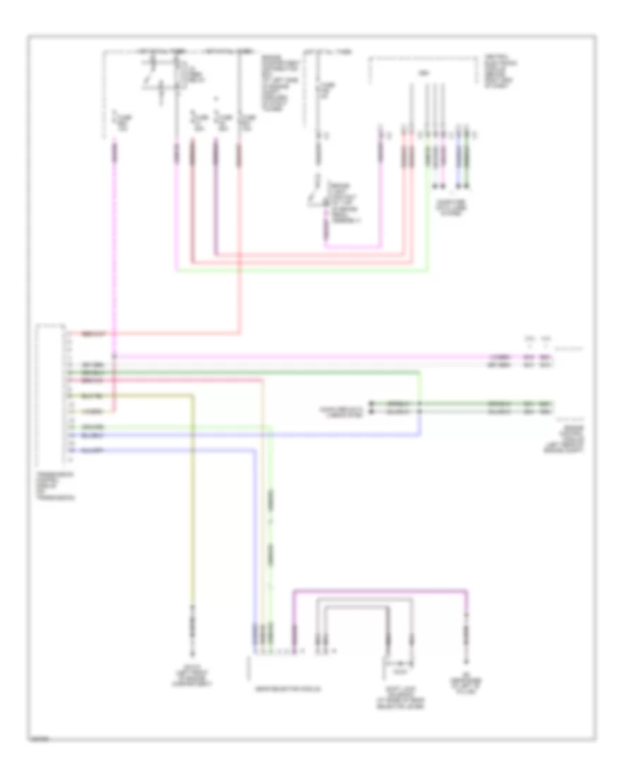
Электросхема стояночного тормоза для Volvo V70 2009


Электросхема стояночного тормоза для Volvo V70 2009 - Список элементов:
- (under driver's door sill)
- Central electronic module (behind right end of dash)
- Computer data lines system
- Fuse b11 30a
- Fuse b12 30a
- G47 (at left rear of luggage compt)
- G83
- Hot at all times
- Left rear brake disc lock motor (at left rear brake assembly)
- Parking brake module (pbm) (left side of trunk)
- Parking brake switch
- Rear electrical center (left rear of luggage compt)
- Right rear brake disc lock motor (at right rear brake assembly)
Электросхема блокировки селектора для Volvo V70 2009
Электросхема блокировки селектора для Volvo V70 2009 - Список элементов:
- 15- feed relay
- 3.2l
- 4.4l
- B13
- B15
- B30
- B41
- B45
- B54
- B58
- Brake light contact (at top of brake pedal assembly)
- Cem
- Central electronic module (behind right end of dash)
- Computer data lines system
- Engine compartment distribution box (at left side of engine compt, forward of strut tower)
- Engine control module (left rear of engine compt)
- Fuse a1 50a
- Fuse a2 50a
- Fuse b20 10a
- Fuse b31 15a
- Fuse f28 5a
- G6 (near base of left "b" pillar)
- Gear selector module
- Gxx10 (left front of engine compartment)
- Hot at all times
- Nca
- Shift lock solenoid (at base of gear selector lever)
- Transmission control module (on transmission)

 English