ПРИБОРНАЯ ПАНЕЛЬ
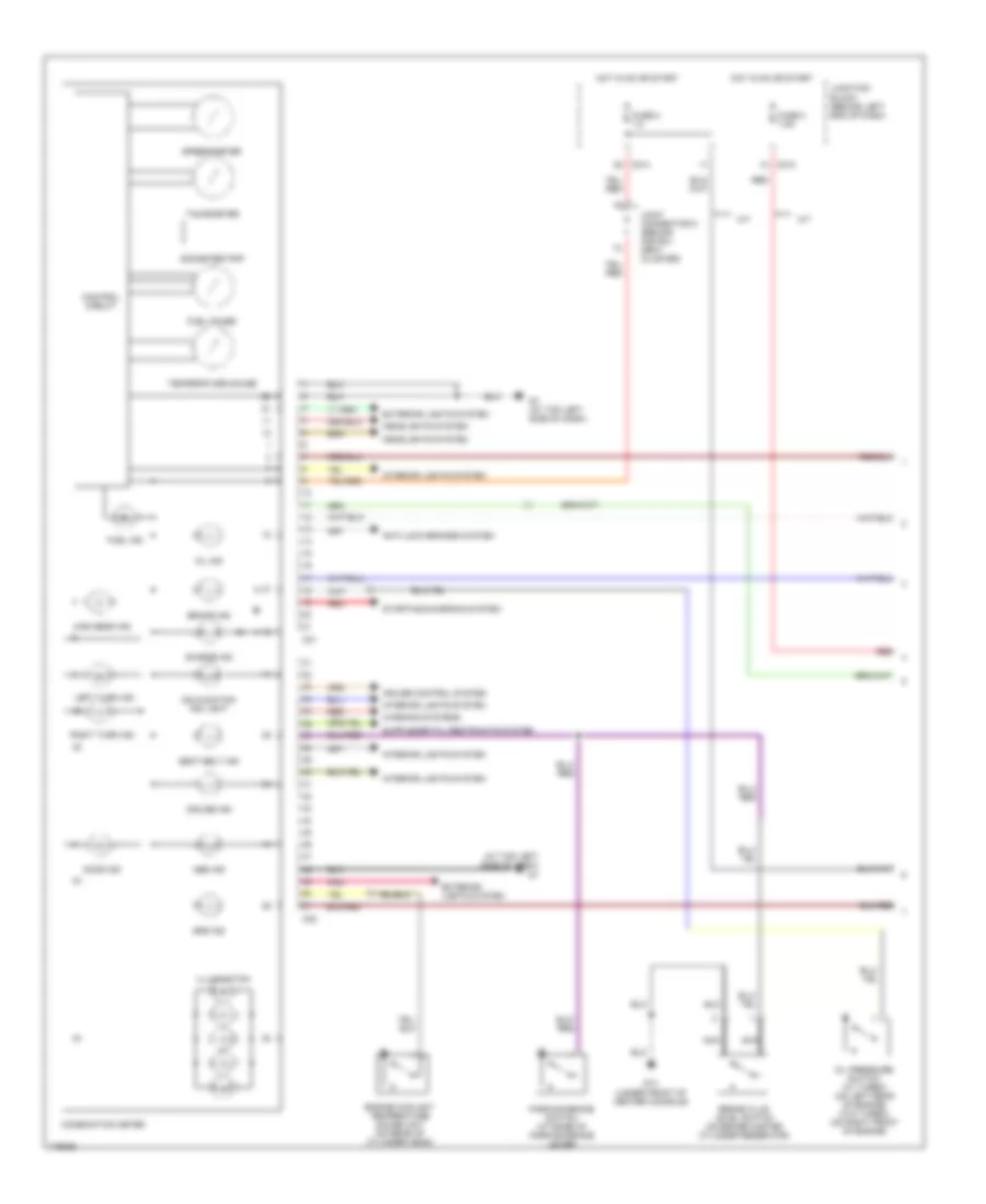
Электросхема панели приборов (1 из 2) для Mitsubishi Lancer LS 2003
Электросхема панели приборов (1 из 2) для Mitsubishi Lancer LS 2003 - Список элементов:
- (at top left side of dash) g7
- A/t
- Abs ind
- Anti-lock brakes system
- Brake fluid level switch (on brake master cylinder reservoir)
- Brake ind
- C01
- C02
- C210
- C214
- Charge ind
- Combination meter
- Control circuit
- Cruise control system
- Cruise ind
- Door ind
- Engine coolant temperature gauge unit (on rear of cylinder head)
- Exterior lights system
- Exterior lights system
- Fuel gauge
- Fuel ind
- Fuse 2 7.5
- Fuse 3 7.5a
- G14 (under front of center console)
- G7 (at top left side of dash)
- Headlights system
- High beam ind
- Hot in on or start
- Illumination
- Interior lights system
- Joint connector 5 (behind instru- ment cluster)
- Junction block (behind left end of dash)
- Left turn ind
- M/t
- Malfunction ind light
- Nca
- Odometer/trip
- Oil ind
- Oil pressure switch (w/ turbo) (on left rear of engine) (w/o turbo) (on right front of engine)
- Parking brake switch (at base of parking brake lever)
- Pnk
- Red
- Right turn ind
- Seat belt ind
- Speedometer
- Srs ind
- Starting/charging system
- Tachometer
- Temperature gauge
- Warning systems
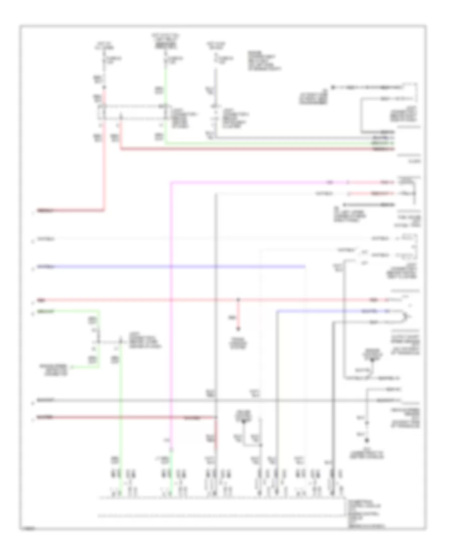
Электросхема панели приборов (2 из 2) для Mitsubishi Lancer LS 2003
Электросхема панели приборов (2 из 2) для Mitsubishi Lancer LS 2003 - Список элементов:
- (a/t)
- (m/t)
- A/t
- C114
- C115
- C117
- C118
- C119
- C120
- Clock
- Cruise control system
- Detection connector
- Engine compartment relay box (on left side of engine compt)
- Engine controls system
- Engine speed
- Fuel gauge unit (in fuel tank)
- Fuse 20 7.5a
- Fuse 22 10a
- Fuse 23 10a
- G14 (under front of center console)
- G3 (at right side of front deck crossmember)
- G9 (at left upper corner of rear shelf panel)
- Hot at all times
- Hot in on or acc
- Hot with tail- light relay energized (front ecu)
- Joint connector 1 (behind center of dash)
- Joint connector 2 (behind instrument cluster)
- Joint connector 3 (behind right side of dash)
- Joint connector 5 (behind instru- ment cluster)
- Joint connector 6 (behind lower center of dash)
- M/t
- Output shaft speed sensor (a/t) (on top right of transaxle)
- Pnk
- Powertrain control module (a/t) engine control module (m/t) (behind glove box)
- Red
- Trans- missions system
- Vehicle speed sensor (m/t) (on right side of transaxle)

 Čeština
 Dansk
Dansk Deutsch
 Ελληνικά
 English
 English
 Español
 Suomi
Suomi Français
 עברית
עברית Hrvatski
 Magyar
 Italiano
 日本語
日本語 한국어
한국어 Nederlands
 Polski
 Português
 Português
 Română
 Русский
 Slovenčina
 Slovenščina
 Svenska
 Türkçe
 中文 (中国)