Противоугонная система Сигнализация
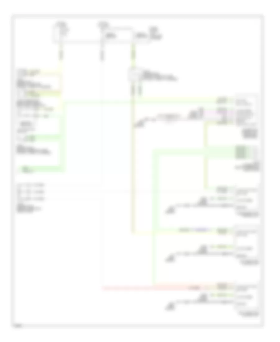
Электросхема противоугонной сигнализации (1 из 2) для Infiniti Q45 2002

Электросхема противоугонной сигнализации (1 из 2) для Infiniti Q45 2002 - Список элементов:
- (body ground)
- (canada)
- (usa)
- 13r
- 19r
- 20b
- 25r
- Accessory
- B17
- B217
- B57
- Battery
- Between full stroke & neutral
- Body control module (bcm) (left kick panel)
- Data line a-3
- Door sw (as)
- Door sw (dr)
- Door sw (rr)
- Driver's door switch
- E62
- Front passenger's door switch
- Fuse 10a
- Fuse 15a
- Fuse 20a
- Fuse block no. 1 (left end of dash)
- Fuse, fusible link & relay box (in right front side of eng compt)
- Ground
- Head- lamp relay
- Headlamp rly
- Headlights system
- High horn
- Hood sw
- Hood switch
- Horn chirp
- Horn relay
- Hot at all times
- Hot in on or accy
- Hot in on or start
- Ignition
- Joint connector 16 (behind upper right side of dash)
- Joint connector 25
- Joint connector 3 (behind left side of dash, near fuse block)
- Joint connector 37
- Joint connector 9 (behind upper left side of dash)
- Keyless ground
- Keyless power
- Keyless sign
- Left rear door lock assembly
- Low horn
- M24 (body ground)
- Muti-remote control receiver
- Red
- Right rear door lock assembly
- Theft ind
- Trunk lid key cylinder switch (unlock switch)
- Trunk room lamp switch
- Trunk sw
- Trunk unlock sw
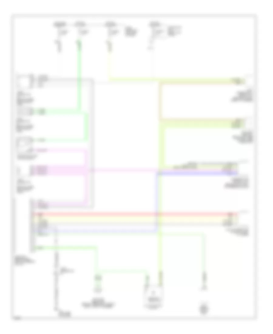
Электросхема противоугонной сигнализации (2 из 2) для Infiniti Q45 2002
Электросхема противоугонной сигнализации (2 из 2) для Infiniti Q45 2002 - Список элементов:
- B17 (body ground)
- B217 (body ground)
- Bat (c/b)
- Battery
- Circuit breaker
- Data line a-3
- Door
- Door locks system
- Driver door control unit (inside left front door)
- Fuse 10a
- Fuse block no. 1 (left end of dash)
- Ground
- Hot at all times
- Joint connector 11 (behind top center of dash, taped to harness)
- Joint connector 15 (behind upper right side of dash)
- Joint connector 20 (behind upper right side of dash, taped to harness)
- Joint connector 21 (behind upper right side of dash)
- Joint connector 3 (behind left side of dash, near fuse block)
- Joint connector 41
- Joint connector 6 (behind upper left side of dash, taped to harness)
- Left rear door control unit
- Local data line
- Lock switch
- Locks
- M114 (body ground)
- M24 (body ground)
- Multifunction switch
- Passenger's door control unit
- Right rear door control unit
- Security indicator
- System
- Unlock sens
- Unlock switch
Электросхема иммобилайзера (NATS) для Infiniti Q45 2002
Электросхема иммобилайзера (NATS) для Infiniti Q45 2002 - Список элементов:
- (right side of dash)
- Ecm (behind glove box)
- F8 (left side of engine)
- Fuse 1 10a
- Fuse 32 10a
- Fuse 6 10a
- Fuse 8 10a
- Fuse block no. 1 (left end of dash)
- Fuse block no. 2 (right kick panel)
- Hot at all times
- Hot in on or start
- Joint con- nector 20 (behind upper right side of dash, tape to harness)
- Joint con- nector 3 (behind left side of dash, near fuse block)
- Joint connector
- Joint connector (behind upper left side of dash)
- Joint connector (behind upper right side of dash)
- Joint connector 11 (behind top center of dash, taped to harness)
- Key switch & key lock solenoid
- M115
- Multi-function switch
- Nats antenna amp (in ignition key cylinder)
- Nats immu (behind dash, left of steering column)
- Red
- Security indicator
- Steering lock control unit (behind dash, right of steering column)