СИСТЕМА АНТИБЛОКИРОВОЧНОЙ ТОРМОЗНОЙ СИСТЕМЫ ABS
Электросхема антиблокировочной тормозной системы АБС (ABS) (1 из 2) для Pontiac Bonneville SSE 1994


Электросхема антиблокировочной тормозной системы АБС (ABS) (1 из 2) для Pontiac Bonneville SSE 1994 - Список элементов:
- #5b
- #6b
- (behind center of
- (center rear of engine
- (left front of
- (left side of engine compartment
- (right side of
- (top of brake pedal support)
- (w/ traction control)
- 10a
- 20a
- 30a
- 40a
- 87a
- Above left horn)
- Abs ind control
- Abs pump relay
- All times
- Antilock diode
- Attached to left strut tower)
- Battery power
- Block
- Brake sw (top of brake
- Composite harness)
- Compt, below left
- Control
- Control module (ebcm/ebtcm)
- Cruise/shift interlock
- Data line
- Electronic brake (& traction)
- Enable input
- Engine compartment,
- Engine, under electronic
- Fluid level input
- Fuse
- G100
- G119
- Ground
- Hot
- Hot at
- Ignition module)
- Ignition power
- In run
- Inst
- Inst panel, taped to
- Left
- Left front
- Left front inlet
- Left front outlet
- Left front sensor
- Left isolation valve
- Left rear
- Left rear inlet
- Left rear outlet
- Left rear sensor
- Main relay
- Main relay control
- Panel
- Pedal support)
- Pnk
- Pnk 1632
- Pnk 849
- Pnk 854
- Pnk 857
- Pres input
- Pump motor control
- Pump motor hi
- Pump motor lo
- Pump on request
- Red
- Red 1633
- Red 342
- Red 885
- Return input
- Right front
- Right front inlet
- Right front outlet
- Right front sensor
- Right isolation valve
- Right rear
- Right rear inlet
- Right rear outlet
- Right rear sensor
- Sense
- Sensor
- Tan
- Tan 800
- Tan 833
- Tan 848
- Tcc/antilock brake sw
- To ind control
- Traction ctrl input
- Transaxle temp input
- Underhood
- Underhood fuse block)
- Wheel speed
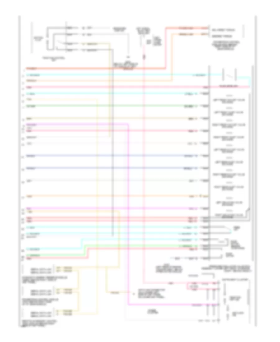
Электросхема антиблокировочной тормозной системы АБС (ABS) (2 из 2) для Pontiac Bonneville SSE 1994
Электросхема антиблокировочной тормозной системы АБС (ABS) (2 из 2) для Pontiac Bonneville SSE 1994 - Список элементов:
- "off" ind
- #1d
- (10/36 ohms)
- (3/6 ohms)
- (5/8 ohms)
- (below left side of
- (derm) (behind right side of
- (dlc) (under left
- (left rear of engine
- (pcm) (behind right side
- (rac) module (behind right
- (w/ dic)
- (w/o dic)
- 1a14
- 20a
- 2c13
- A11
- A15
- Antilock
- Assembly (lower left front of engine
- B11
- B13
- Block
- Bulb test
- Cluster
- Compartment, below
- Compt, behind headlt)
- Data link connector
- Delivered torque
- Desired torque
- Diagnostic energy reserve module
- Fluid level sw
- Fuse
- G100
- G200
- Gages
- Head/park
- Hot in run,
- I/p, middle of left
- Illum
- Ind
- Inst
- Inst panel)
- Instrument cluster
- Lamp sw
- Left front inlet valve
- Left front outlet valve
- Left isolation valve
- Left rear inlet valve
- Left rear outlet valve
- Module (pcm) (behind
- Motor
- Nca
- Near shroud)
- Of i/p, near shroud)
- On lower inst panel)
- Or start
- Panel
- Pnk
- Powertrain control
- Powertrain control module
- Pres
- Pressure modulator valve (pmv)
- Pump
- Red
- Remote accessory control
- Right front inlet valve
- Right front outlet valve
- Right isolation valve
- Right rear inlet valve
- Right rear outlet valve
- Right side of i/p
- Sensor
- Serial data link
- Shroud)
- Side of inst panel)
- Side of inst panel,
- Switch
- Tan
- Tan 800
- Traction
- Traction control
- Wiper motor module)

 Русский