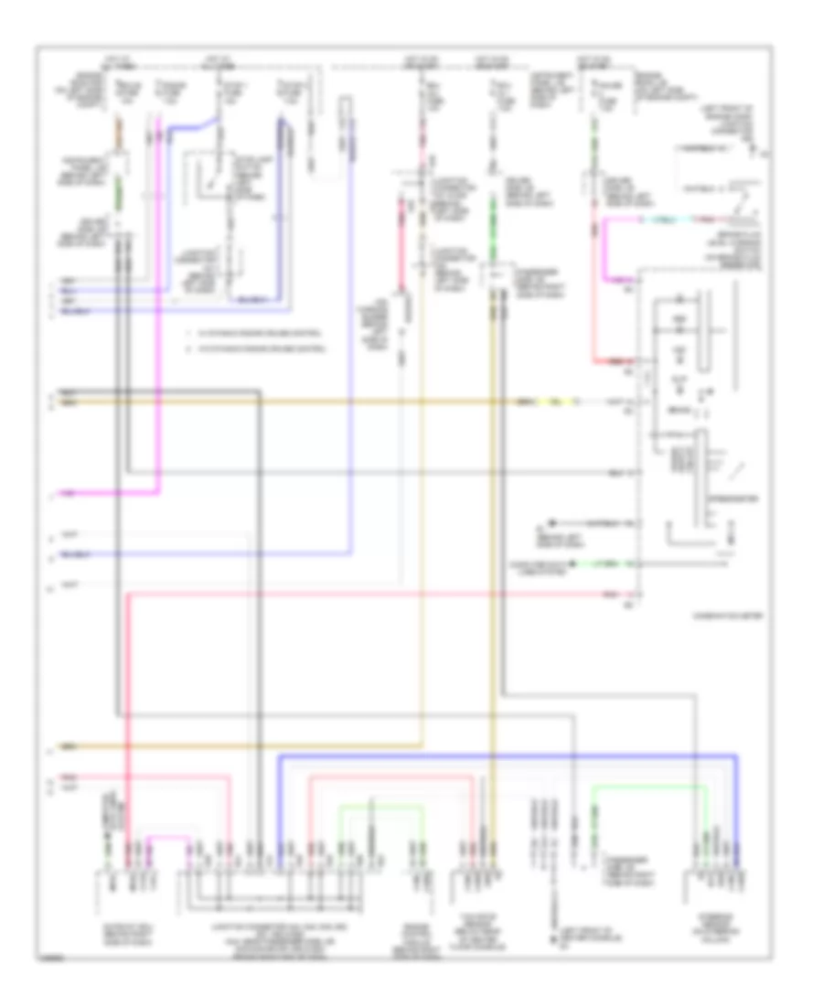
СИСТЕМА АНТИБЛОКИРОВОЧНОЙ ТОРМОЗНОЙ СИСТЕМЫ ABS
Электросхема антиблокировочной тормозной системы АБС (ABS), С Регулирование тягового усилия (1 из 2) для Toyota Avalon Touring 2005

Электросхема антиблокировочной тормозной системы АБС (ABS), С Регулирование тягового усилия (1 из 2) для Toyota Avalon Touring 2005 - Список элементов:
- +bs
- A41
- A6 (at right end of dash)
- Abs/ vsc 1 fuse 50a
- Abs/ vsc 2 fuse 30a
- Brk relay (w/ dynamic radar cruise control)
- C14
- Canh
- Canl
- D/g
- D13
- D46
- Data link connector 3 (at lower left side of dash)
- Ecu ig 2 fuse 10a
- Engine room r/b (on left side of engine compt)
- F19
- Fl+
- Fl-
- Fr+
- Fr-
- Gnd1
- Gnd2
- Headlamp leveling ecu (behind left side of dash)
- Hot at all times
- Hot in on or start
- Ig1
- Instrument panel j/b (behind left side of dash)
- Junction connector a41 & d46 (behind left side of dash)
- Junction connector a42 (behind left side of dash)
- Junction connector a54 (right front of engine compt)
- Left front speed sensor (mounted on left front wheel hub assembly)
- Left rear speed sensor (mounted on left rear wheel hub assembly)
- Mrf
- Nca
- Parking brake switch (on parking brake pedal assembly)
- Passenger side j/b (behind right side of dash)
- Pkb
- Pnk
- Red
- Right front speed sensor (mounted on right front wheel hub assembly)
- Right rear speed sensor (mounted on right rear wheel hub assembly)
- Rl+
- Rl-
- Rlo
- Rr+
- Rr-
- Rro
- Skid control ecu w/ actuator (at right side of engine compt)
- Sp1
- Stp1
- Stp2
- Stpo
- Vsc 1 relay
- Vsc 2 relay
- W/ dynamic radar cruise control
- Wfse
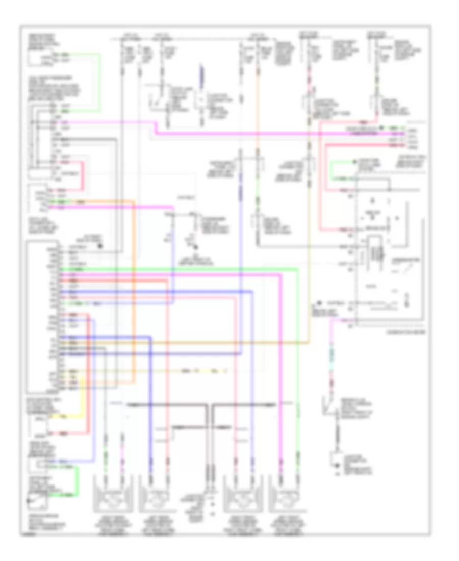
Электросхема антиблокировочной тормозной системы АБС (ABS), С Регулирование тягового усилия (2 из 2) для Toyota Avalon Touring 2005
Электросхема антиблокировочной тормозной системы АБС (ABS), С Регулирование тягового усилия (2 из 2) для Toyota Avalon Touring 2005 - Список элементов:
- (left front of center console) d2
- (left front of engine comp) junction connector a52
- A44
- Abs
- B10
- B11
- B16
- Bat
- Brake
- Brake fluid level warning switch (on brake fluid reservoir)
- Buzzer
- C13
- Ca1h
- Ca1l
- Canh
- Canl
- Circuit
- Combination meter
- Computer data lines system
- D10
- D20
- D46
- D48
- D49
- D50
- D51
- D52
- Driver side j/b (behind left side of dash)
- E1 (behind left side of dash)
- E14
- E28
- Ecu ig 1 fuse 7.5a
- Ecu ig 2 fuse 10a
- Ecu-b fuse 10a
- Engine control module (behind right side of dash)
- Engine room j/b (on left side of engine compt)
- Engine room r/b (on left side of engine compt)
- Ess
- F11
- F15
- F19
- G12
- Gateway ecu (behind right side of dash)
- Gauge fuse 7.5a
- Gnd
- Hot at all times
- Hot in on or start
- I11
- Instrument panel j/b (behind left side of dash)
- Junction connector a41 & d46 (behind a41
- Junction connector a41 (behind left side of dash)
- Junction connector a42 (behind left side of dash)
- Junction connector a44, d48, d49, d50, d51, d52 & e28 (a44: near passenger side j/b) (d48,d49,d50,d51,d52 & e28: behind right end of dash)
- K15
- Left side of dash)
- Mpd1
- Mpd2
- Mpx +b
- Passenger side j/b (behind right side of dash)
- Pnk
- Radar fuse 7.5a
- Red
- Slip
- Speedometer
- Steering sensor (on steering column)
- Stop 1 fuse 15a
- Stop 2 fuse 7.5a
- Stop lamp switch (behind left side of dash)
- Vsc
- Vsc warning buzzer (behind left side of dash)
- W/ dynamic radar cruise control
- W/o dynamic radar cruise control
- Yaw rate sensor (below rear of center floor console)
Электросхема антиблокировочной тормозной системы АБС (ABS), без Регулирование тягового усилия для Toyota Avalon Touring 2005
Электросхема антиблокировочной тормозной системы АБС (ABS), без Регулирование тягового усилия для Toyota Avalon Touring 2005 - Список элементов:
- (a44: near passenger side j/b) (d48,d49,d50,d51,d52 & e28: behind right end of dash) junction connector a44, d50, d51, d52 & e28
- (at right end of dash) a6
- (behind right side of dash)
- (behind right side of dash) engine control module
- +bm
- +bs
- A41
- A44
- Abs ind
- Abs/ vsc 1 fuse 50a
- Abs/ vsc 2 fuse 30a
- Brake fluid level warning switch (right front of engine compt)
- Brake ind
- C13
- C14
- Ca1h
- Ca1l
- Canh
- Canl
- Combination meter
- Computer data lines system
- D/g
- D10
- D13
- D2 (left front of center console)
- D25
- D46
- D50
- D51
- Data link connector 3 (at lower left side of dash)
- Driver side j/b (behind left side of dash)
- E1 (behind left side of dash)
- E28
- Ecu ig 2 fuse 10a
- Ecu-b fuse 10a
- Engine room j/b (on left side of engine compt)
- Engine room r/b (on left side of engine compt)
- F15
- F19
- Fl+
- Fl-
- Fr+
- Fr-
- G12
- Gateway ecu
- Gauge fuse 7.5a
- Gnd1
- Gnd2
- Headlamp leveling ecu (behind left side of dash)
- Hot at all times
- Hot in on or start
- I11
- Ig1
- Instrument panel j/b (behind left side of dash)
- Instrument panel j/b (on left side of engine compt)
- Junction connector a41 & d46 (behind left side of dash)
- Junction connector a41 (behind left side of dash)
- Junction connector a42 (behind left side of dash)
- Junction connector a52 (engine compt left front of)
- Junction connector a54 (right front of engine compt)
- K15
- Left front speed sensor (mounted on left front wheel hub assembly)
- Left rear speed sensor (mounted on left rear wheel hub assembly)
- Mpd1
- Mpd2
- Mpx +b
- Nca
- Parking brake switch (on parking brake pedal assembly)
- Passenger side j/b (behind right side of dash)
- Pkb
- Pnk
- Red
- Right front speed sensor (mounted on right front wheel hub assembly)
- Right rear speed sensor (mounted on right rear wheel hub assembly)
- Rl+
- Rl-
- Rlo
- Rr+
- Rr-
- Rro
- Sil
- Skid control ecu w/ actuator (at right side of engine compt)
- Sp1
- Spdl
- Spdr
- Speedometer
- Stop 1 fuse 15a
- Stop fuse 7.5a
- Stop lamp switch (behind left side of dash)
- Stp