СИСТЕМА АНТИБЛОКИРОВОЧНОЙ ТОРМОЗНОЙ СИСТЕМЫ ABS
Электросхема антиблокировочной тормозной системы АБС (ABS) (1 из 2) для Volkswagen GTI VR6 1995

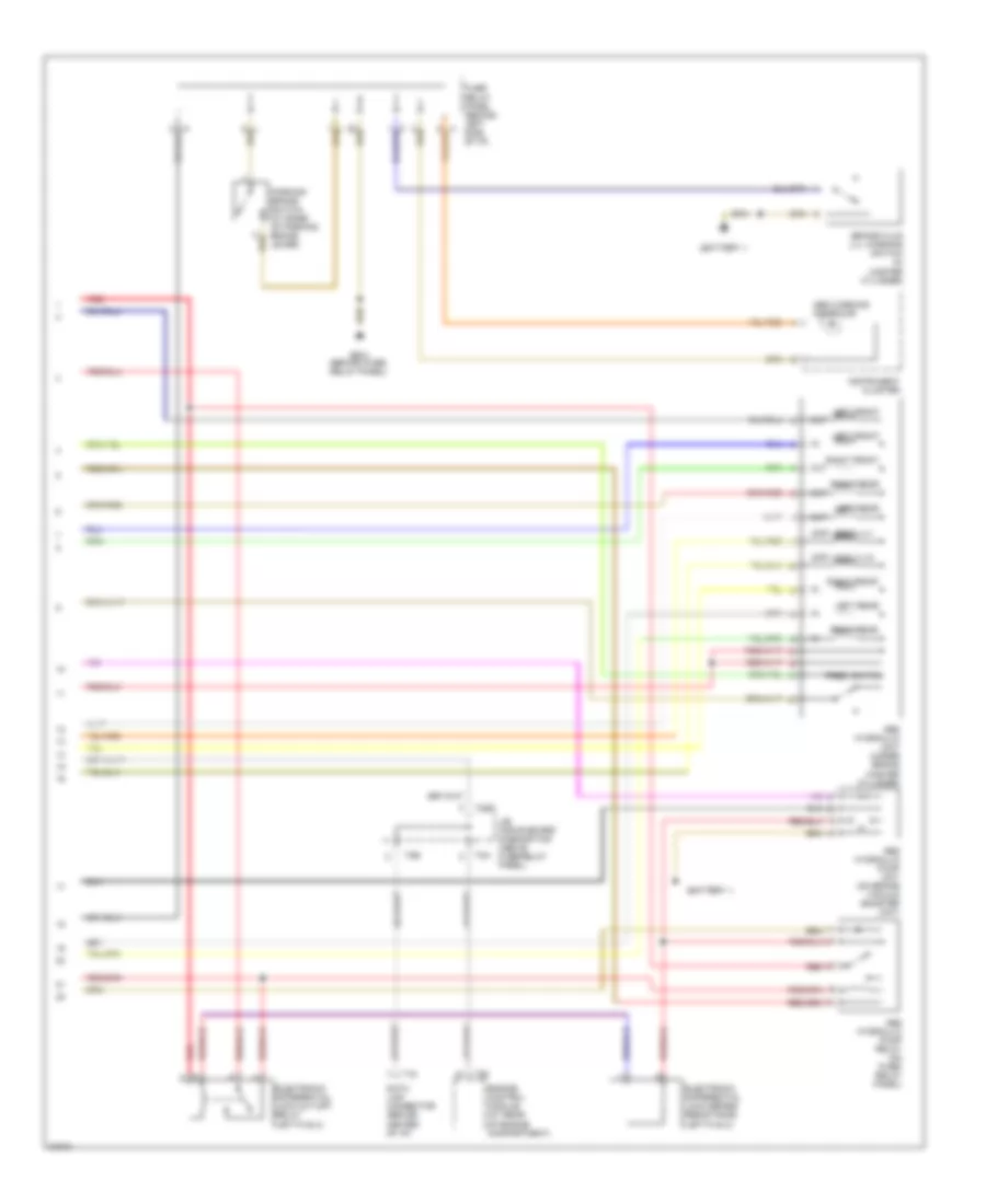
Электросхема антиблокировочной тормозной системы АБС (ABS) (1 из 2) для Volkswagen GTI VR6 1995 - Список элементов:
- (battery -)
- Abs control module (behind right kick panel)
- Abs main relay (on fuse/ relay panel)
- Auxiliary fuse panel (behind left side of i/p)
- Brake light switch (top of brake pedal support)
- Brake pedal position sensor (mounted on brake booster unit)
- Fuse 20 10a
- Fuse 30a
- Fuse/ relay panel (behind left side of i/p)
- G304 (below left rear seat)
- Hot at all times
- Hot w/ unloader relay energized
- Left front speed sensor capacitor
- Left front wheel speed sensor
- Left rear wheel speed sensor
- Nca
- Red
- Right front speed sensor capacitor
- Right front wheel speed sensor
- Right rear wheel speed sensor
Электросхема антиблокировочной тормозной системы АБС (ABS) (2 из 2) для Volkswagen GTI VR6 1995
Электросхема антиблокировочной тормозной системы АБС (ABS) (2 из 2) для Volkswagen GTI VR6 1995 - Список элементов:
- (battery -)
- Abs hydraulic pump relay (on fuse/ relay panel)
- Abs hydraulic pump unit (on brake vacuum booster unit)
- Abs hydraulic unit (under brake master cylinder)
- Abs warning indicator
- Brake fluid lvl warning switch (in master cylinder)
- Data link connector (behind center of i/p)
- Diff lock vlv1
- Diff lock vlv2
- Electronic differential lock cut-off relay (jetta glx)
- Electronic differential lock series resistance (jetta glx)
- Engine control module (at rear of engine compartment)
- Fuse/ relay panel (behind left side of i/p)
- G202 (behind fuse/ relay panel)
- Instrument cluster
- J/b for on-board diagnostics (above fuse/relay panel)
- Left front
- Left rear
- Out
- Parking brake switch (at base of parking brake lever)
- Pres. switch
- Red
- Right front
- Right rear
- T16
- T2a
- T2b
- T2dd
- T68