СИСТЕМА КОНДИЦИОНЕРА
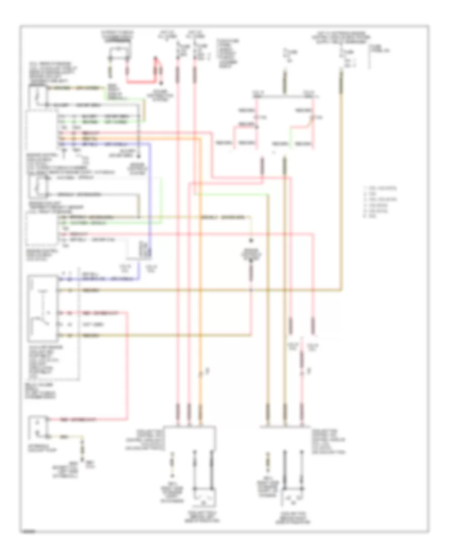
Электросхема кондиционера (1 из 4) для Audi A6 3.2 2011

Электросхема кондиционера (1 из 4) для Audi A6 3.2 2011 - Список элементов:
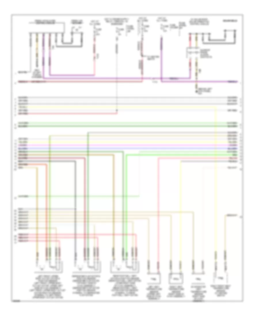
Электросхема кондиционера (2 из 4) для Audi A6 3.2 2011
Электросхема кондиционера (2 из 4) для Audi A6 3.2 2011 - Список элементов:
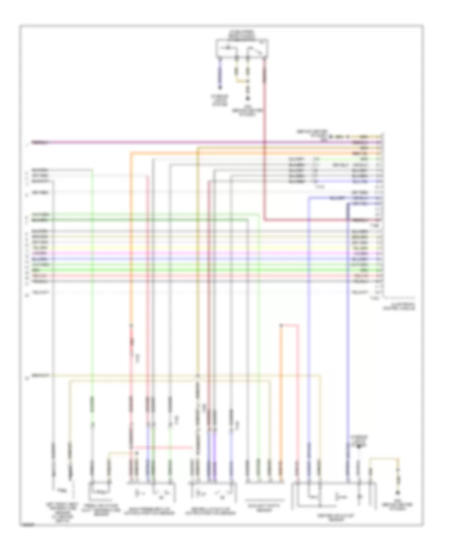
Электросхема кондиционера (3 из 4) для Audi A6 3.2 2011
Электросхема кондиционера (3 из 4) для Audi A6 3.2 2011 - Список элементов:
Электросхема кондиционера (4 из 4) для Audi A6 3.2 2011
Электросхема кондиционера (4 из 4) для Audi A6 3.2 2011 - Список элементов: