СИСТЕМА КОНДИЦИОНЕРА
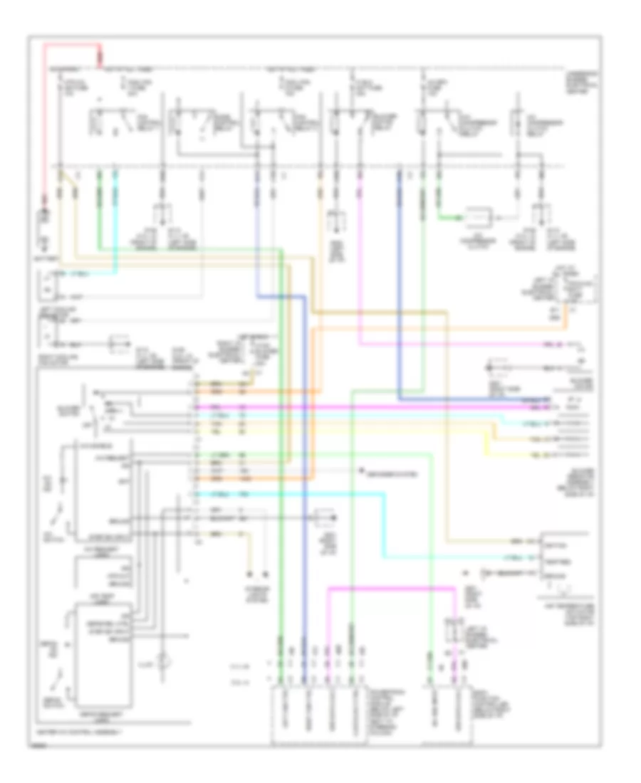
Электросхема кондиционера для Chevrolet Malibu LS 1997
Электросхема кондиционера для Chevrolet Malibu LS 1997 - Список элементов:
- 2.4l l4
- 3.1l v6
- A/c bfc fuse 10a
- A/c compressor clutch
- A/c compressor clutch relay
- A/c disable
- A/c on ind
- A/c req input
- A/c request
- A/c request logic
- A/c switch
- A10
- A11
- Air temp logic
- Air temperature actuator (top right side of i/p)
- B11
- Bat
- Battery
- Blower motor
- Blower motor relay
- Blower resistor assembly (below right side of i/p)
- Blower switch
- Body function controller (below right side of i/p)
- C10
- Clutch rly ctrl
- Cool fan 1 fuse 30a
- Cool fan 2 fuse 15a
- D10
- D11
- Defog on ind
- Defog rel ctrl
- Defog request logic
- Defog switch
- Defogger system
- F11
- Fan control relay 1
- Fan control relay 2
- G112 (3.1l v6) (left side of engine)
- G125 (2.4l l4) (front of engine)
- G201 (right side of i/p)
- G202 (left side of i/p)
- Ground
- Heater a/c control assembly
- Hi blo mot fuse 30a
- Hot at all times
- Hot in run
- Htr a/c ign fuse 10a
- Htr out
- Hvac blower fuse 20a
- Ign
- Ignition
- Illum
- Interior lights system
- Ipc/hvac batt fuse 10a
- Left cooling fan motor
- Left fan ctrl
- Left i/p bussed electrical center
- Mode control relay
- Off
- Powertrain control module (below left side of i/p, next to steering column)
- Red
- Right cooling fan motor
- Right fan ctrl
- Right i/p bussed electrical center
- Ser data cls 2
- Step dim input
- Tan
- Temp req
- Underhood bussed electrical center
 Čeština
 Dansk
Dansk Deutsch
 Ελληνικά
 English
 Español
 Suomi
Suomi Français
 Français
 עברית
עברית Hrvatski
 Magyar
 Italiano
 日本語
日本語 한국어
한국어 Nederlands
 Polski
 Português
 Português
 Română
 Русский
 Slovenčina
 Slovenščina
 Svenska
 Türkçe
 中文 (中国)
 English