Русский
СИСТЕМА КОНДИЦИОНЕРА
Электросхема кондиционера (1 из 3) для Lincoln Navigator 2008


Электросхема кондиционера (1 из 3) для Lincoln Navigator 2008 - Список элементов:
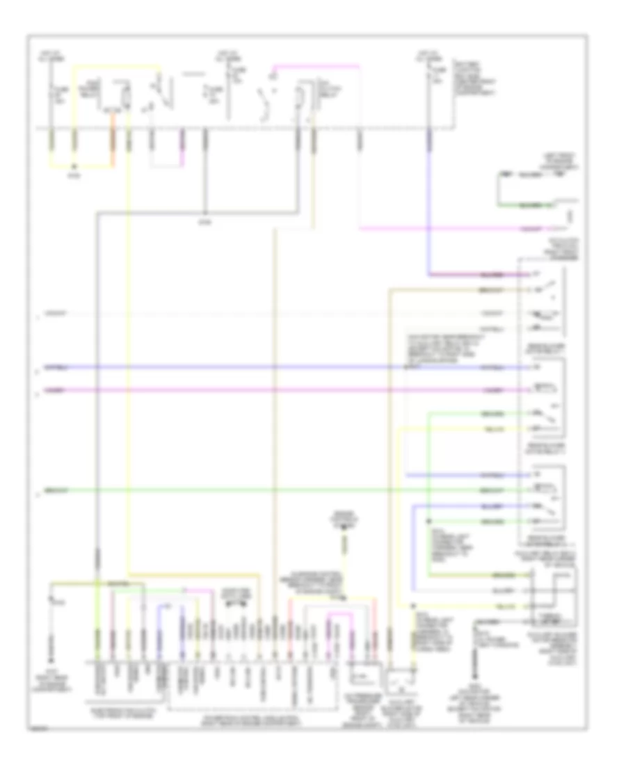
Электросхема кондиционера (2 из 3) для Lincoln Navigator 2008
Электросхема кондиционера (2 из 3) для Lincoln Navigator 2008 - Список элементов:
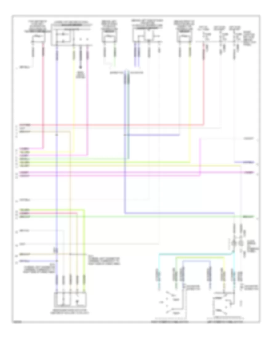
Электросхема кондиционера (3 из 3) для Lincoln Navigator 2008
Электросхема кондиционера (3 из 3) для Lincoln Navigator 2008 - Список элементов: