СИСТЕМА КОНДИЦИОНЕРА
Электросхема кондиционера для Oldsmobile Ciera SL 1996
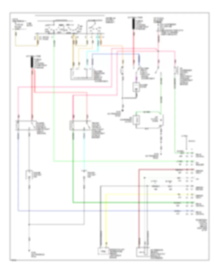
Электросхема кондиционера для Oldsmobile Ciera SL 1996 - Список элементов:
- (buick) (olds)
- +5v
- A/c clutch diode
- A/c compressor clutch
- A/c compressor control relay (right front of engine compartment on relay bracket)
- A/c compressor in line fuse 10a (behind right side of i/p, taped to harness near fuse block)
- A/c pressure sensor (right front of engine, on compressor)
- A/c request
- Bi-lv
- Blower motor
- Blower relay (right front of engine compartment)
- Blower resistors (right rear of engine compartment)
- Blower switch
- C2 c2
- Def
- E d
- Engine coolant temperature sensor (left side of engine)
- Fuse block
- G129 (on transaxle stud)
- Heater-a/c control assembly
- Hot at all times
- Hot in accy or run
- Hot in run, bulb test or start
- Htr
- Htr-a/c fuse 20a
- L4 vin 4
- Max
- Mode switch
- Norm
- Off
- Pnk
- Powertrain control module (behind right side of i/p)
- Primary coolant fan
- Primary coolant fan relay (right front of engine compartment on relay bracket)
- Pusher coolant fan
- Pusher coolant fan relay (behind right side of radiator)
- Red
- Relay control
- Sensor input
- Sensor return
- Tan
- V6 vin m
- Vent
 English