СИСТЕМА КОНДИЦИОНЕРА
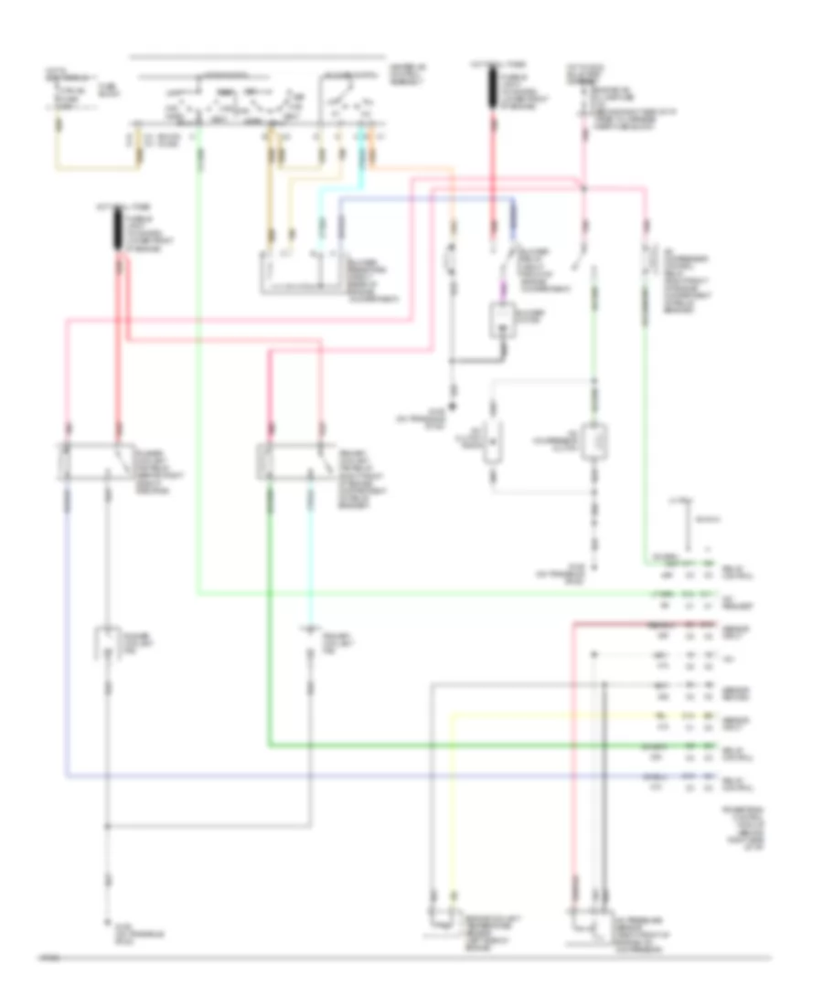
Электросхема кондиционера для Oldsmobile Cutlass Ciera SL 1995
Электросхема кондиционера для Oldsmobile Cutlass Ciera SL 1995 - Список элементов:
- (buick) (olds)
- +5v
- A/c clutch diode
- A/c compressor clutch
- A/c compressor control relay (right front of engine compartment on relay bracket)
- A/c pressure sensor (right front of engine, on compressor)
- A/c request
- B12
- Bi-lv
- Blower motor
- Blower relay (right front of engine compartment)
- Blower resistors (right rear of engine compartment)
- Blower switch
- C10
- C11
- C2 c2
- D11
- D12
- Def
- E d
- Engine coolant temperature sensor (left side of engine)
- Engine/ a/c in line fuse 10a (behind right side of i/p, taped to harness near fuse block)
- Fuse block
- G129 (on transaxle stud)
- Heater-a/c control assembly
- Hot at all times
- Hot in accy or run
- Hot in run, bulb test or start
- Htr
- Htr-a/c fuse 20a
- L4 vin 4
- Max
- Mode switch
- Norm
- Off
- Pnk
- Powertrain control module (behind right side of i/p)
- Primary coolant fan
- Primary coolant fan relay (right front of engine compartment on relay bracket)
- Pusher coolant fan
- Pusher coolant fan relay (behind right side of radiator)
- Red
- Relay control
- Sensor input
- Sensor return
- Tan
- V6 vin m
- Vent
 Čeština
 Dansk
Dansk Deutsch
 Ελληνικά
 English
 Español
 Suomi
Suomi Français
 Français
 עברית
עברית Hrvatski
 Magyar
 Italiano
 日本語
日本語 한국어
한국어 Nederlands
 Polski
 Português
 Português
 Română
 Русский
 Slovenčina
 Slovenščina
 Svenska
 Türkçe
 中文 (中国)
 English