СИСТЕМА КРУИЗКОНТРОЛЯ
4.0L
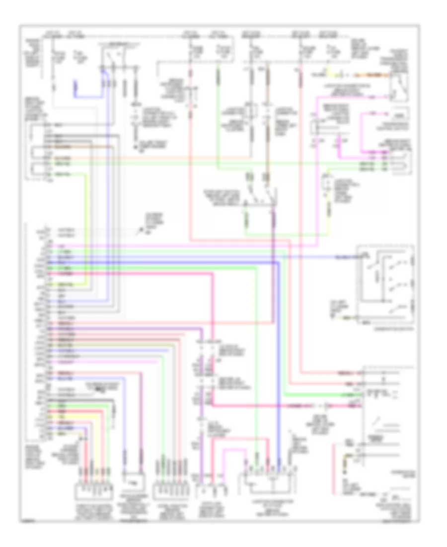
4.0L, Электросхема системы круизконтроля для Toyota 4Runner SR5 2005

4.0L, Электросхема системы круизконтроля для Toyota 4Runner SR5 2005 - Список элементов:
- (behind center of dash)
- (behind instrument cluster) junction connector 8 & 9
- (behind right center of dash) center j/b
- (behind right end of dash) junction connector 29 & 30
- (behind right end of dash) junction connector 31 & 32
- (on left front inner fender) eb
- (on rear
- (on rear of right cylinder head)
- (on rear of right cylinder head) ee
- (on right side of transmission) park/neutral position switch
- +b2
- +bm
- +res
- -set
- A j29
- Accel position sensor (behind left side of dash)
- Batt
- C10
- Cancel
- Canh
- Canl
- Ccs
- Center j/b (behind right center of dash)
- Combination meter
- Combination switch
- Cruise ind
- Data link connector 3 (below left side of dash)
- Dome fuse 10a
- Driver side j/b (behind lower left end of dash)
- E01
- E02
- Ecc
- Ef (on rear of left cylinder head)
- Efi fuse 20a
- Efi relay
- Engine control module (behind right end of dash)
- Engine room r/b (on left side of engine compt)
- Ep1
- Ep2
- Epa
- Epa2
- Etcs fuse 10a
- Gauge fuse 7.5a
- Ge01
- Hot at all times
- Hot in on or start
- I8 (in dash harness, behind upper right side of dash)
- Ig1 fuse 15a
- Ign fuse 10a
- Igsw
- Ih (behind left center of dash)
- Instrument cluster)
- J/c 18 (behind instrument cluster)
- J/c 28 (behind right side of dash, near firewall grommet)
- J/c 29 & 30 (behind right end of dash)
- J29
- J30
- J30 e
- J31
- J32
- J50
- J51
- J52
- Junction connector (behind b
- Junction connector (behind upper left end of dash)
- Junction connector 2 & 3 (on left front of engine compt, near battery)
- Junction connector 25 (behind right center of dash)
- Junction connector 4 (behind upper left end of dash)
- Junction connector 50, 51 & 52
- K11
- Mrel
- Nca
- Nssd
- Of right cylinder head)
- On-off
- Pnk
- Red
- S28
- Skid control ecu with actuator (left rear of engine compartment)
- Sp1
- Sp2+
- Sp2-
- Spd
- Speedo- meter
- St1-
- Stop fuse 10a
- Stoplight switch (behind left side of dash, above brake pedal)
- Stp
- Throttle control motor & throttle position sensor (on throttle body)
- Transmission control switch
- Vcp1
- Vcp2
- Vcpa
- Vehicle speed sensor (electronically controlled transmission) (on transmission)
- Vpa
- Vpa1
- Vpa2
- Vta1
- Vta2
4.7L
4.7L, Электросхема системы круизконтроля для Toyota 4Runner SR5 2005
4.7L, Электросхема системы круизконтроля для Toyota 4Runner SR5 2005 - Список элементов:
- (behind center of dash)
- (behind instrument cluster) junction connector 8 & 9
- (behind right center of dash) center j/b
- (behind right end of dash) junction connector 29 & 30
- (behind right end of dash) junction connector 31 & 32
- (on left
- (on left front inner fender) eb
- (on rear of right cylinder head)
- (on rear of right cylinder head) ee
- (on right side of transmission) park/neutral position switch
- +b2
- +bm
- +res
- -set
- 4wd
- A j29
- Accel position sensor (behind left side of dash)
- Batt
- C10
- Cancel
- Canh
- Canl
- Ccs
- Center j/b (behind right center of dash)
- Combination meter
- Combination switch
- Cruise ind
- Cylinder head)
- Data link connector 3 (below left side of dash)
- Dome fuse 10a
- Driver side j/b (behind lower left end of dash)
- E01
- E02
- Ecc
- Ed (on left cylinder head)
- Efi fuse 20a
- Efi relay
- Engine control module (behind right end of dash)
- Engine room r/b (on left side of engine compt)
- Ep1
- Ep2
- Epa
- Epa2
- Etcs fuse 10a
- Gauge fuse 7.5a
- Ge01
- Hot at all times
- Hot in on or start
- I8 (in dash harness, behind upper right side of dash)
- Ig1 fuse 15a
- Ign fuse 10a
- Igsw
- Ih (behind left center of dash)
- Instrument cluster)
- J/c 18 (behind instrument cluster)
- J/c 29 & 30 (behind right end of dash)
- J29
- J30
- J30 e
- J31
- J32
- J50
- J51
- J52
- Junction connector (behind b
- Junction connector (behind upper left end of dash)
- Junction connector 2 & 3 (on left front of engine compt, near battery)
- Junction connector 25 (behind right center of dash)
- Junction connector 4 (behind upper left end of dash)
- Junction connector 50, 51 & 52
- K11
- Mrel
- Nca
- Nssd
- On-off
- Pnk
- Red
- S28
- Skid control ecu with actuator (left rear of engine compartment)
- Sp1
- Sp2+
- Sp2-
- Spd
- Speedo- meter
- St1-
- Stop fuse 10a
- Stoplight switch (behind left side of dash, above brake pedal)
- Stp
- Throttle control motor & throttle position sensor (on throttle body)
- Transmission control switch
- Vcp1
- Vcp2
- Vcpa
- Vehicle speed sensor (electronically controlled transmission) (on transmission)
- Vpa
- Vpa1
- Vpa2
- Vta1
- Vta2