СИСТЕМА КРУИЗКОНТРОЛЯ
3.4L
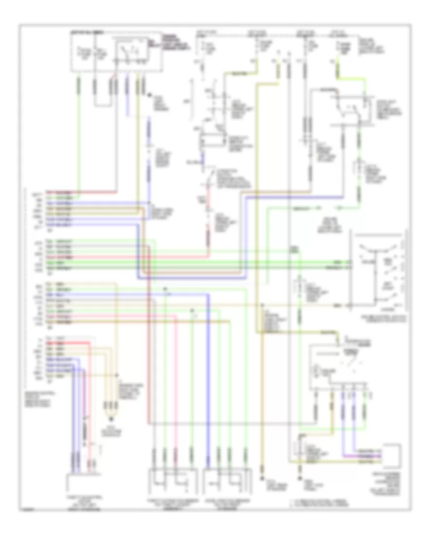
3.4L, Электросхема системы круизконтроля для Toyota Tundra SR5 2000

3.4L, Электросхема системы круизконтроля для Toyota Tundra SR5 2000 - Список элементов:
- (a/t)
- (a/t) (a/t) (a/t) (a/t) (a/t)
- (california)
- (except calif)
- (m/t)
- A11 e3
- A12
- A13
- A7 e3
- Acc fuse 15a
- B b b b b
- B24 e4
- B4 e4
- Cancel
- Ccs
- Cms
- Combination meter
- Control circuit
- Cruise control actuator w/ ecu (on right side of engine compt)
- Cruise control clutch switch (under left side of dash)
- Cruise control ind
- Cruise control switch (combination switch)
- D17 e6
- D8 e6
- Data link connector 1 (left side of engine intake manifold)
- Diode (a/t) (behind left side of dash)
- Drive position switch (park/neutral position switch) (on transmission)
- Driver side j/b (lower left end of dash)
- Ect
- Ecu-ig fuse 5a
- Engine control module (behind right side of dash)
- G11
- G13
- G200
- G200 (left kick panel)
- G203
- Gauge fuse 10a
- Gnd
- Gnd 1
- Hot at all times
- Hot in on & acc
- Hot in on & start
- I4 (dash harn, right end of dash)
- Idl
- Idlo
- J/c 12 (behind top end of dash)
- J/c 13 (right kick panel)
- J/c 3 (left kick panel)
- J/c 5 (behind left side of dash)
- J/c 7 (behind left side of dash)
- J/c 8 (behind left side of dash)
- J/c 8 j/c 8 j/c 8 j/c 8 j/c 8 behind left behind left behind left behind left behind left side of dash) side of dash) side of dash) side of dash) side of dash)
- J/c 9 behind left side of dash)
- Main
- Od1
- Op3
- Resume/ accel
- Set/ coast
- Spd
- Stop fuse 15a
- Stop- light switch (on braket, above brake pedal)
- Stp-
- Vehicle speed sensor (combination meter)
4.7L
4.7L, Электросхема системы круизконтроля для Toyota Tundra SR5 2000
4.7L, Электросхема системы круизконтроля для Toyota Tundra SR5 2000 - Список элементов:
- +b1
- +bm
- A10
- A12
- A13
- A16
- A19
- Acc fuse 15a
- Accel position sensor (on top front of engine)
- B15
- B19
- B23
- B24
- Batt
- Braided
- C c
- C11
- C13
- Cancel
- Ccs
- Cl+
- Cl-
- Cms
- Combination meter
- Cruise
- Cruise control switch (combination switch)
- Cruise ind
- D position switch (park/neutral position switch) (on transmission)
- D13
- D17
- D18
- D20
- D21
- Diode (a/t) (behind combination meter)
- Driver side j/b (lower left end of dash)
- E01
- E02
- E03
- E21
- E24
- E29
- E30
- E31
- Efi 1 fuse 15a
- Efi efi efi efi relay relay relay relay
- Engine control module (behind right side of dash)
- Engine engine engine room r/b room r/b room r/b (left side of (left side of (left side of engine compt) engine compt) engine compt)
- Etcs fuse 15a
- F11
- G102 (left front fender)
- G11
- G114 (left rear of engine)
- G131 (on intake manifold)
- G200 (left kick panel)
- Gauge fuse 10a
- Ge01
- Hot at all times
- Hot at all times hot at all times hot at all times hot at all times
- Hot in acc & on
- Hot in on or start
- I10 (engine harn, right side of dash at firewall)
- I5 (dash harn, right side of dash)
- I7 (engine harn, right side of dash, at firewall)
- Ign fuse 5a
- Igsw
- J/c 1 (on left side of engine compt)
- J/c 12 (behind upper right side of dash)
- J/c 7 (behind upper left side of dash)
- J/c 8 (behind upper left side of dash)
- J/c 9 (behind upper left side of dash)
- Me01
- Mrel
- Red
- Res/ acc
- Set/ coast
- Spd
- Speedo- meter
- St1-
- Stop stop stop fuse fuse fuse 15a 15a 15a
- Stoplight switch (on bracket, above brake pedal)
- Stp
- Throttle control motor (on top left front of engine)
- Throttle position sensor (on throttle body assembly)
- Vehicle speed sensor (combination meter) (on left side of transmission)
- Vpa
- Vpa2
- Vta
- Vta2
- W/ remote control mirror w/o remote control mirror