СИСТЕМА ОХЛАЖДЕНИЯ
Электросхема системы охлаждения для Mercedes-Benz CLS550 4Matic 2014
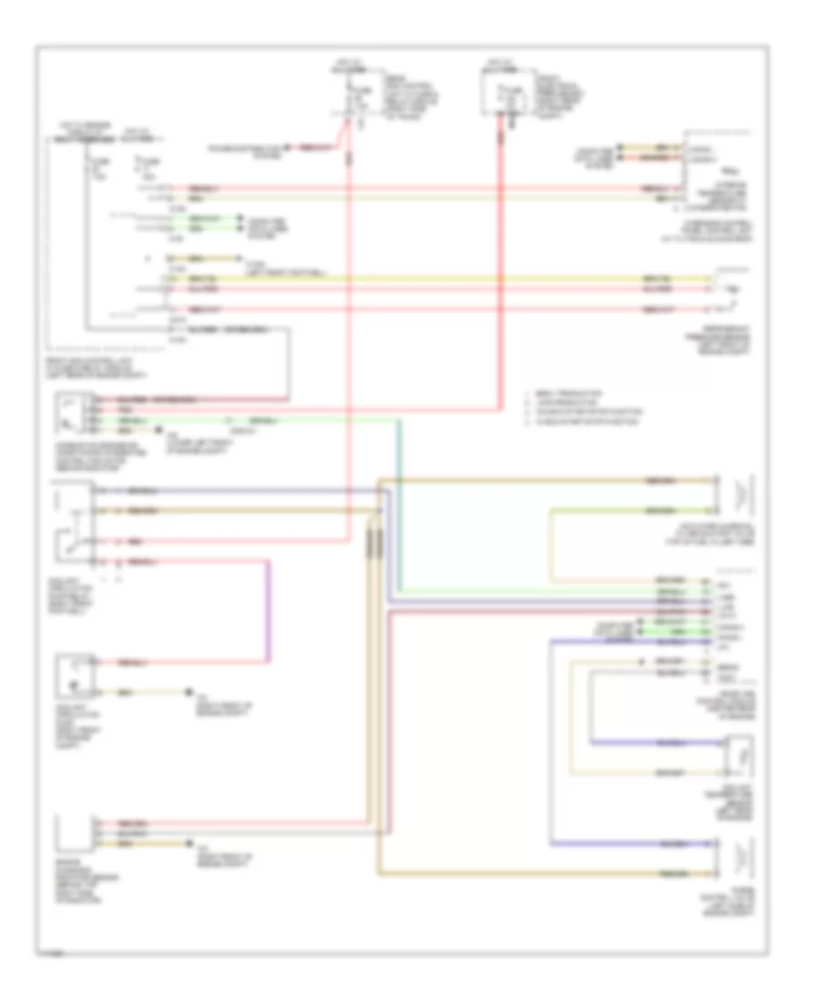
Электросхема системы охлаждения для Mercedes-Benz CLS550 4Matic 2014 - Список элементов:
- 30a
- 7.5a
- Activated charcoal filter shutoff valve (top of fuel filler tube)
- Akv
- C13d
- C14m
- C19i
- C21m
- C3i
- Can-b h
- Can-b l
- Can-e h
- Can-e l
- Combustion engine/air conditioning integrated control fan motor (behind radiator)
- Computer data lines system
- Coolant circulation pump (right front of engine compt)
- Coolant circulation pump relay (right front footwell)
- Coolant temperature sensor (left rear of engine)
- Early production
- Engine diagnosis radiator sensor (behind top right side of radiator)
- Front electrical prefuse box (right rear of engine compt)
- Front sam control unit w/ fuse & relay module (left rear of engine compt)
- Fuse
- Fuse 100a mr4
- Fuse 7.5a
- Hot at all times
- Hot w/ engine circuit 87 relay energized
- Interior temperature sensor w/ integrated fan
- Late production
- Lin c1
- Llkr
- Lpv
- Lues
- Me-sfi (me) control module (center rear of engine)
- Overhead control panel control unit (w/ tilting & sliding roof)
- Power distribution system
- Purge control valve (left side of engine compt)
- Rear sam control unit w/ fuse & relay module (right side of trunk)
- Red
- Refrigerant pressure sensor (left front of engine compt)
- Senm3
- Tmot
- W/ eco start/stop function
- W/o eco start/stop function
- W15/5 (left front footwell)
- W2 (right front of engine compt)
- W9 (lower left front of engine compt)
- X25/2-c1
 English