СИСТЕМА ОХЛАЖДЕНИЯ
Электросхема системы охлаждения для Mercedes-Benz E400 Hybrid 2014
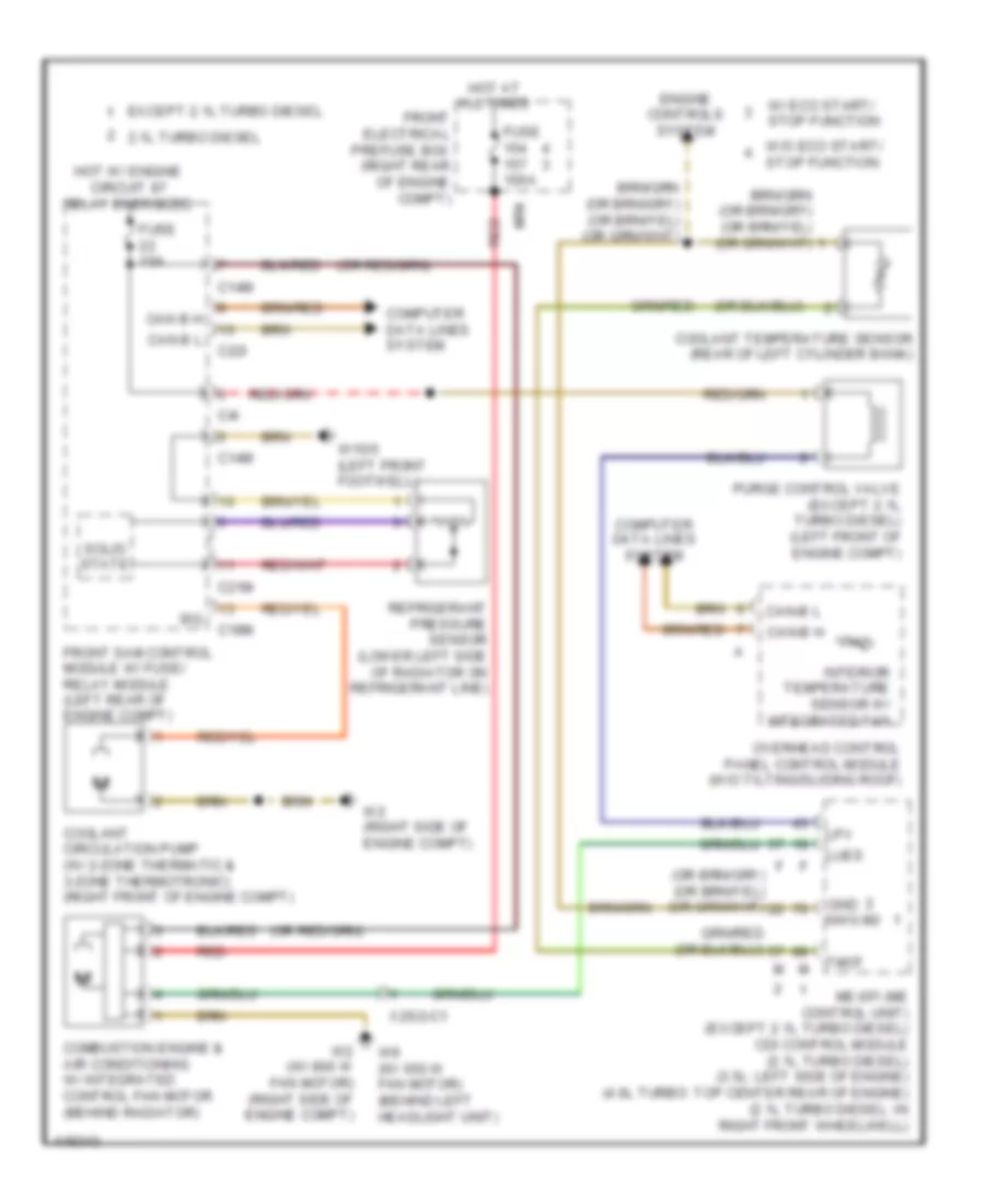
Электросхема системы охлаждения для Mercedes-Benz E400 Hybrid 2014 - Список элементов:
- 2.1l turbo diesel
- C14m
- C18m
- C21m
- C22i
- C4i
- Can b h
- Can b l
- Can-b h
- Can-b l
- Combustion engine & air conditioning w/ integrated control fan motor (behind radiator)
- Computer data lines system
- Coolant circulation pump (w/ 2-zone thermatic & 3-zone thermotronic) (right front of engine compt)
- Coolant temperature sensor (rear of left cylinder bank)
- Engine controls system
- Except 2.1l turbo diesel
- Front electrical prefuse box (right rear of engine compt)
- Front sam control module w/ fuse/ relay module (left rear of engine compt)
- Fuse 100a
- Fuse 15a
- Gnd nwg m2
- Hot at all times
- Hot w/ engine circuit 87 relay energized
- Interior temperature sensor w/ integrated fan
- Lpv
- Lues
- Me-sfi (me control unit) (except 2.1l turbo diesel) cdi control module (2.1l turbo diesel) (3.5l: left side of engine) (4.6l turbo: top center rear of engine) (2.1l turbo diesel: in right front wheelwell)
- Mr4
- Overhead control panel control module (w/o tilting/sliding roof)
- Purge control valve (except 2.1l turbo diesel) (left front of engine compt)
- Red
- Refrigerant pressure sensor (lower left side of radiator on refrigerant line)
- Sig
- Solid state
- Tmot
- W/ eco start/ stop function
- W/o eco start/ stop function
- W15/5 (left front footwell)
- W2 (right side of engine compt)
- W2 (w/ 800 w fan motor) (right side of engine compt)
- W9 (w/ 650 w fan motor) (behind left headlight unit)
- X25/2-c1
 English