СИСТЕМА ОХЛАЖДЕНИЯ
Электросхема системы охлаждения для Mercedes-Benz ML500 2005
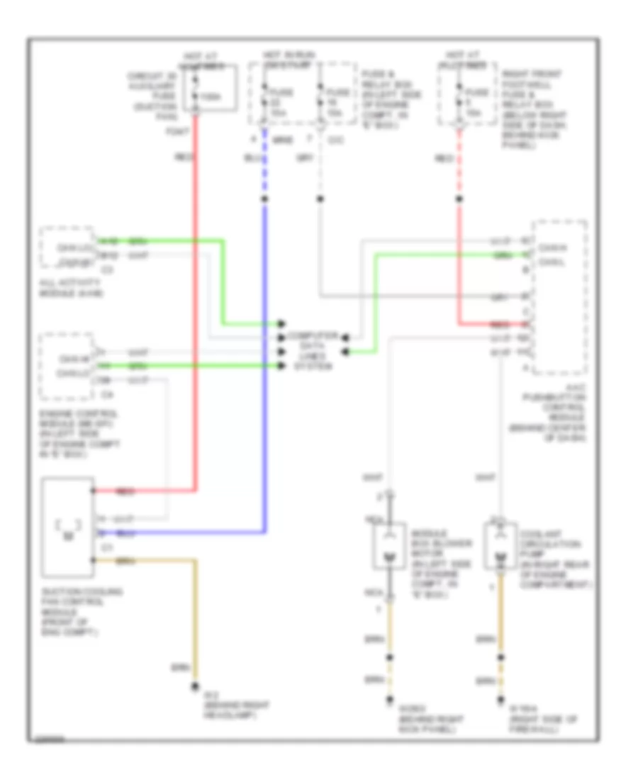
Электросхема системы охлаждения для Mercedes-Benz ML500 2005 - Список элементов:
- 100a
- A12
- Aac pushbutton control module (behind center of dash)
- All activity module (aam)
- B12
- C/c
- Can h
- Can hi
- Can l
- Can lo
- Circuit 30 auxiliary fuse (suction fan)
- Computer data lines system
- Coolant circulation pump (in right rear of engine compartment)
- Engine control module (me-sfi) (in left side of engine compt in "e" box)
- F24/7
- Fuse & relay box (in left side of engine compt, in "e" box)
- Fuse 15a
- Hot at all times
- Hot in run or start
- Module box blower motor (in left side of engine compt, in "e" box)
- Mr/e
- Nca
- Red
- Right front footwell fuse & relay box (below right side of dash, behind kick panel)
- Suction cooling fan control module (front of eng compt)
- W16/4 (right side of firewall)
- W2 (behind right headlamp)
- W29/2 (behind right kick panel)
 English