СИСТЕМА ПЕРЕДАЧИ ДАННЫХ
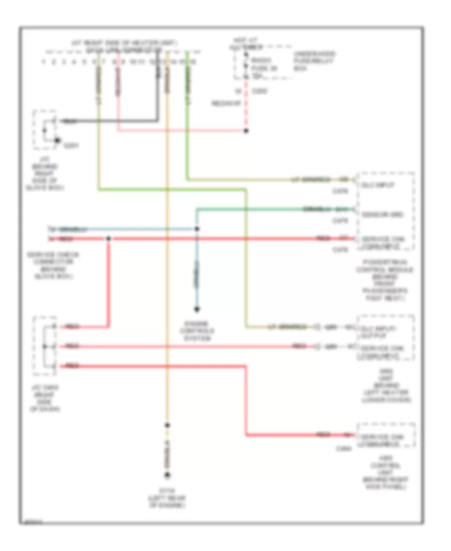
Электросхема компьютерной линии передачи данных CAN для Honda Odyssey EX 1997
Электросхема компьютерной линии передачи данных CAN для Honda Odyssey EX 1997 - Список элементов:
 English
Электросхема компьютерной линии передачи данных CAN для Honda Odyssey EX 1997
Электросхема компьютерной линии передачи данных CAN для Honda Odyssey EX 1997 - Список элементов: