СИСТЕМА ПЕРЕДАЧИ ДАННЫХ
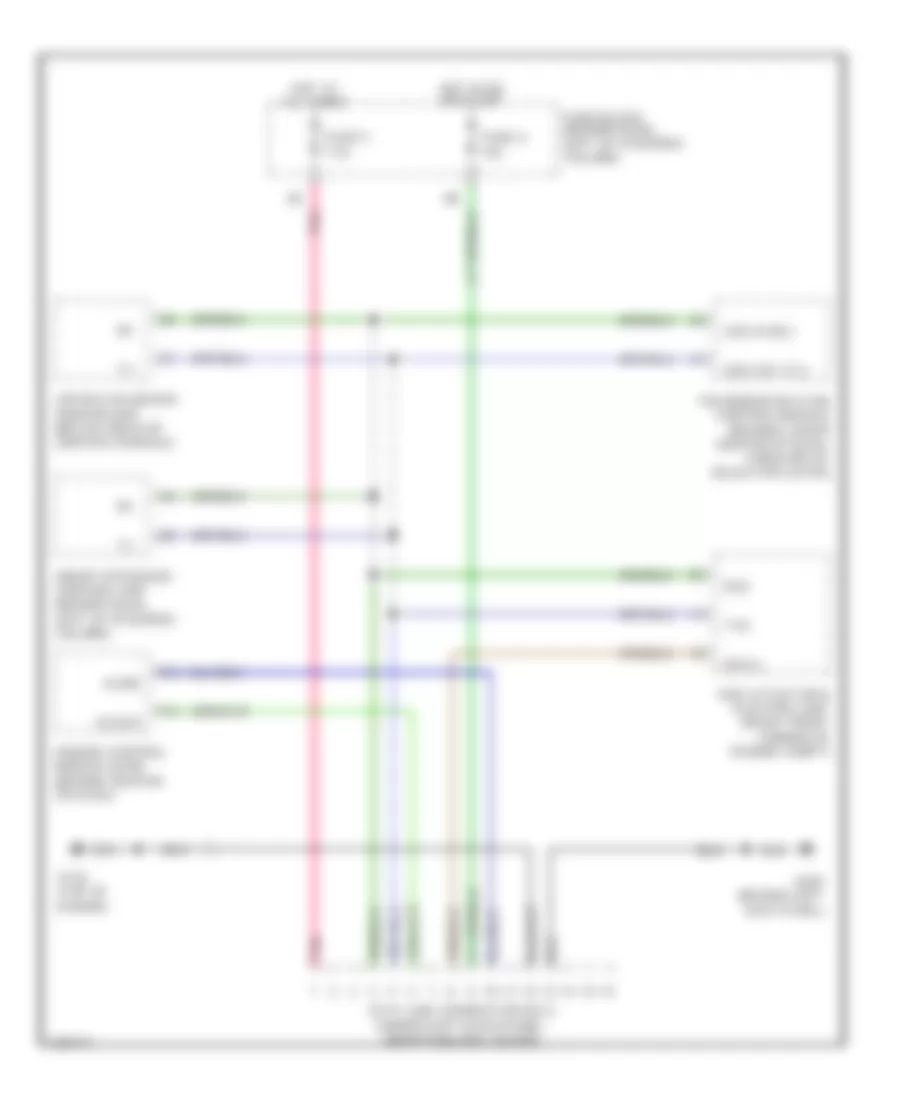
Электросхема компьютерной линии передачи данных CAN для Infiniti G20 2000
Электросхема компьютерной линии передачи данных CAN для Infiniti G20 2000 - Список элементов:
 English
Электросхема компьютерной линии передачи данных CAN для Infiniti G20 2000
Электросхема компьютерной линии передачи данных CAN для Infiniti G20 2000 - Список элементов: