СИСТЕМА ПЕРЕДАЧИ ДАННЫХ
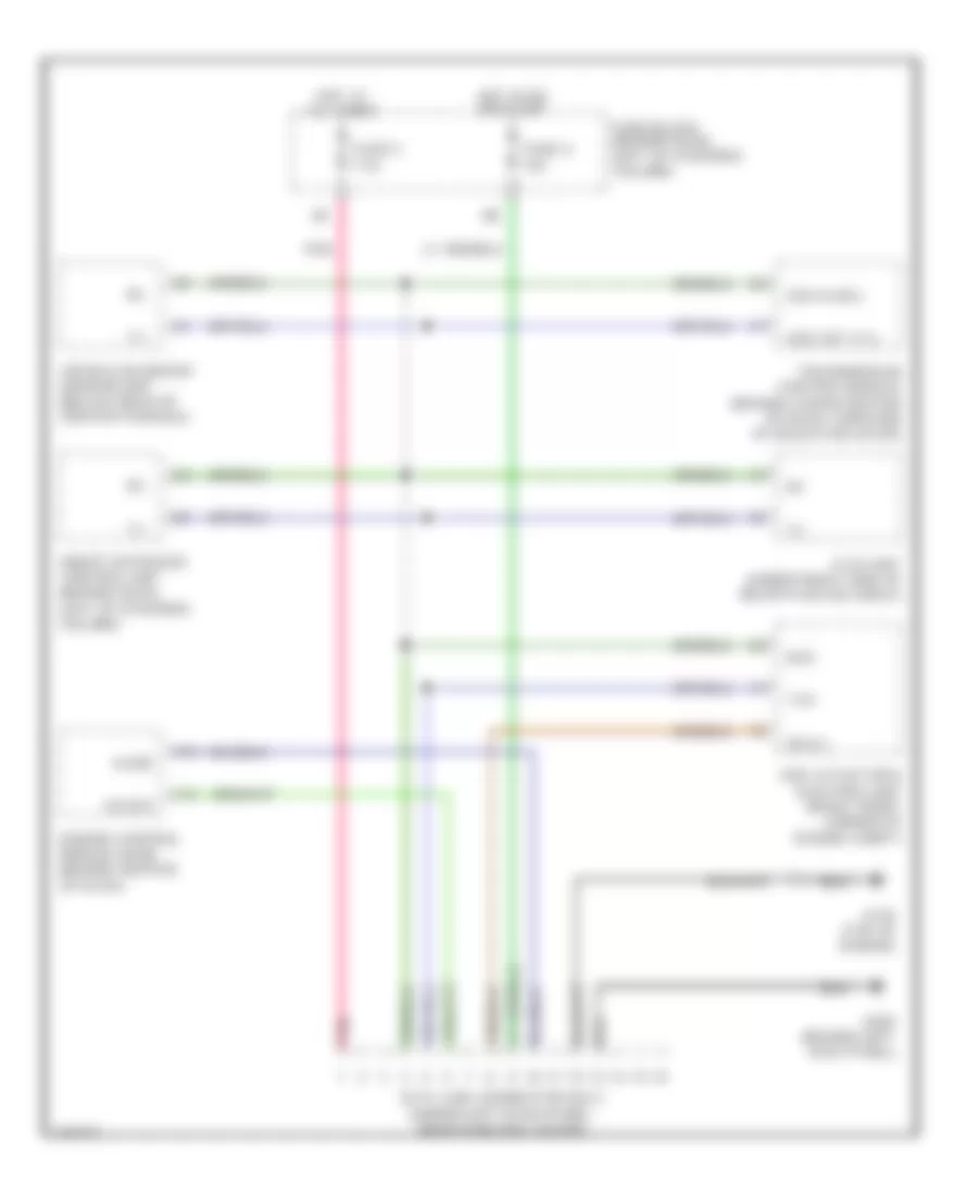
Электросхема компьютерной линии передачи данных CAN для Infiniti G20 t 2001
Электросхема компьютерной линии передачи данных CAN для Infiniti G20 t 2001 - Список элементов:
- Abs actuator & electric unit (right front corner of engine compt)
- Adjsw
- Air bag diagnosis sensor unit (below rear of center console)
- Data link connector (dlc) (under left dash panel, near fuse box cover)
- Diag l
- Engine control module (ecm) (behind center of dash)
- Fuse 5 7.5a
- Fuse 8 10a
- Fuse block (behind dash, left of steering column)
- G134 (top of engine)
- G200 (behind left kick panel)
- Hot at all times
- Hot in on or start
- Ivcs unit (under right side of rear package shelf)
- Kline
- Pnk
- Rxd
- Smart entrance control unit (behind dash, left of steering column)
- Sss in (rx)
- Sss out (tx)
- Transmission control module (behind lower center of dash, forward of selector lever)
- Txd
 English