СИСТЕМА ПЕРЕДАЧИ ДАННЫХ
Электросхема компьютерной линии передачи данных CAN для Lincoln Continental 2000
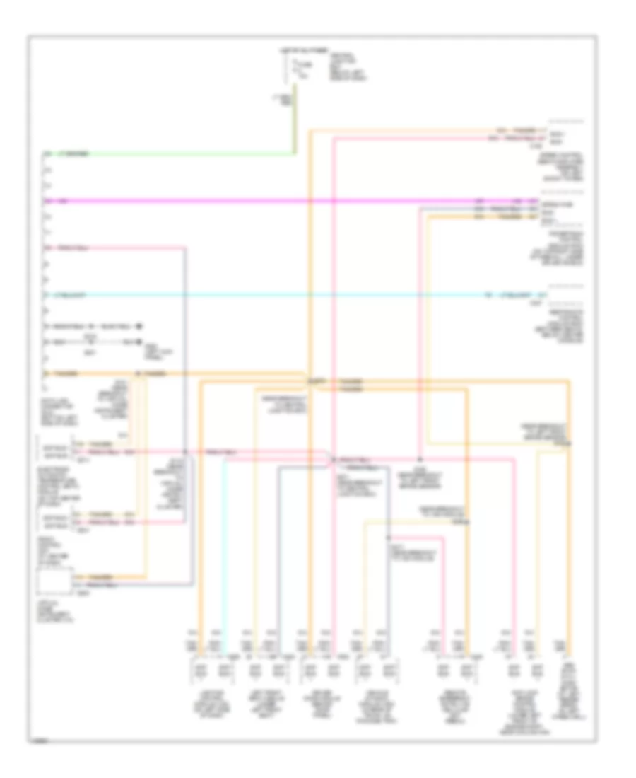
Электросхема компьютерной линии передачи данных CAN для Lincoln Continental 2000 - Список элементов:
- (near breakout to central junction box)
- (near breakout to left front brake sensor) s162
- (near breakout to vdm module)
- Abs evac & fill conn- ector (at left fender apron, on left wheelwell)
- Anti-lock brake control module (lower left front of engine compt, near cooling fan)
- Bus +
- Bus -
- C152
- C206
- C224
- C256
- C274
- C327
- C342
- C448
- C524
- Central junction box (below left side of dash)
- Data link connector (dlc) (bottom left side of dash)
- Driver door module (behind door panel)
- Electronic automatic temperature control (eatc) module (on top center of dash)
- Eprom pwr
- Front control unit (at center of dash)
- Fuse 10a
- G200 (left kick panel)
- Hot at all times
- Left front seat module (under left front seat)
- Lighting control module (lcm) (on left side of dash)
- Powertrain control module (pcm) (on top right side of firewall, under splash shield)
- Remote emergency satellite cellular unit (rescu)
- Restraints control module (rcm) (between seats, below center console)
- S101 (near breakout to virtual image instrument cluster)
- S118 (near breakout to virtual image instru- ment cluster)
- S160 (near breakout to left front brake sensor)
- S201
- S216
- S271 (near breakout to central junction box)
- S273
- S417 (near breakout to vdm module)
- S468
- Scp bus +
- Scp bus -
- Speed control servo/amplifier assembly (on left shock tower)
- Vehicle dynamic module (vdm) (in rear of trunk, on package tray)
- Virtual image instrument cluster (vic)
 Русский
 English