СИСТЕМА ПЕРЕДАЧИ ДАННЫХ
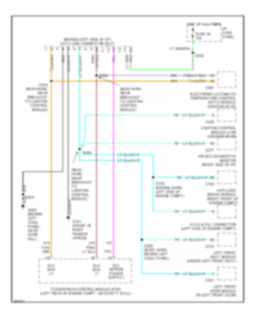
Электросхема компьютерной линии передачи данных CAN для Lincoln Town Car Cartier 1997
Электросхема компьютерной линии передачи данных CAN для Lincoln Town Car Cartier 1997 - Список элементов:
- (behind left side of i/p) data link connector (dlc)
- (main harn, near breakout to lighting control module)
- (right front of engine compt)
- Air bag diagnostic monitor (right side of i/p)
- Anti-lock brake module
- C162
- C220
- C277
- C281
- C313
- C521
- Dlc bus (+)
- Dlc bus (-)
- Electronic automatic temperature control (eatc) module (center of i/p)
- Evac & fill connector (left side of engine compt)
- Fuse 18 10a
- G101 (front of right fender apron)
- G200 (behind left cowl panel, near door sill)
- Hot at all times
- I/p fuse panel
- Left front door module (in left front door)
- Left front seat module (under left front seat)
- Lighting control module (lcm) (center of i/p)
- Powertrain control module (pcm) (left rear of engine compt, on safety wall)
- S150 (engine harn, left side of engine compt)
- S206
- S252
- S254 (main harn, near breakout to lighting control module)
- S262
- S265 (body harn, behind left cowl panel)
- S266
 Čeština
 Dansk
Dansk Deutsch
 Ελληνικά
 English
 Español
 Suomi
Suomi Français
 Français
 עברית
עברית Hrvatski
 Magyar
 Italiano
 日本語
日本語 한국어
한국어 Nederlands
 Polski
 Português
 Português
 Română
 Русский
 Slovenčina
 Slovenščina
 Svenska
 Türkçe
 中文 (中国)
 English