СИСТЕМА ПЕРЕДАЧИ ДАННЫХ
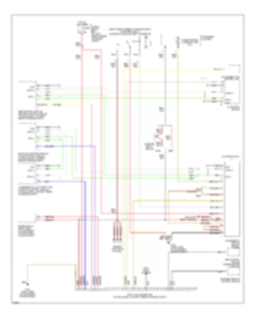
Электросхема компьютерной линии передачи данных CAN для Mercedes-Benz E500 1994
Электросхема компьютерной линии передачи данных CAN для Mercedes-Benz E500 1994 - Список элементов:
- (mil)
- (right rear corner of engine compt) (california only) diagnostic module test connector
- 26 (or 16)
- A/c pushbutton control unit
- Abs control module/ abs/asr control module (in module box, on right rear of engine compt)
- Anti- theft system
- Base module (right side of component compartment, in module box)
- California only
- Can
- Can h+
- Can l-
- Check engine warning lamp
- Controls
- Data link connector (in module box, on right rear of engine compt)
- Di control module
- Diagnogstic module (behind dash)
- E420
- E500
- Ea/cc/isc control module/ cc/isc control module (in module box, on right rear of engine compt)
- Engine
- Fuel pump relay module
- Fuse & relay box (on left rear corner of engine compt)
- Fuse 8a
- G103 (right side of component compartment)
- Hot at all times
- Infrared remote control module
- Instrument cluster
- Lh sequential multiport fuel injection control module (in module box, on right rear of engine compt)
- Nca
- Red
- Red/
- Srs control module (under center console)
- Starter relay module
- System
 English