СИСТЕМА ПЕРЕДАЧИ ДАННЫХ
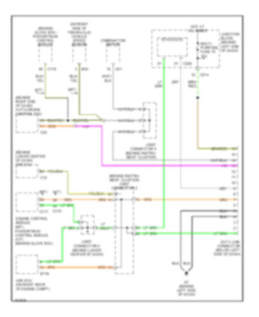
Электросхема компьютерной линии передачи данных CAN для Mitsubishi Lancer LS 2002
Электросхема компьютерной линии передачи данных CAN для Mitsubishi Lancer LS 2002 - Список элементов:
 English
Электросхема компьютерной линии передачи данных CAN для Mitsubishi Lancer LS 2002
Электросхема компьютерной линии передачи данных CAN для Mitsubishi Lancer LS 2002 - Список элементов: