СИСТЕМА ПЕРЕДАЧИ ДАННЫХ
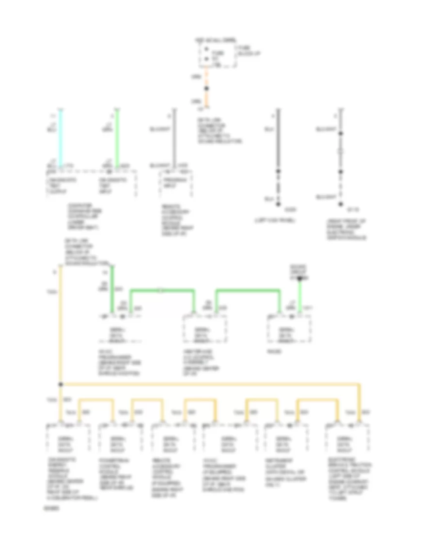
схема соединителя канала связи для Oldsmobile Ninety-Eight Regency 1994
схема соединителя канала связи для Oldsmobile Ninety-Eight Regency 1994 - Список элементов:
- (left kick panel)
- (right front of engine, under electronic ignition module)
- A11
- B11
- Computer command ride controller (under driver seat)
- Data link connector (below i/p, attached to sound insulator)
- Diagnostic energy reserve module (behind center of i/p, on right side of accelerator pedal)
- Diagnostic test input
- Diagnostic test output
- E10
- E11
- Electronic brake & traction control module (left side of engine compart- ment, attached to left strut tower)
- Fuse 9c 10a
- Fuse block:i/p
- G119
- G200
- Heater and a/c control assembly (behind center of i/p)
- Hot at all times
- Hvac programmer (behind right side of i/p, near shroud and pcm)
- Hvac programmer (if equipped) (behind right side of i/p, near shroud and pcm)
- Instrument cluster (with digital or gauges cluster only)
- Powertrain control module (behind right side of i/p) near shroud)
- Program input
- Radio
- Remote accessory control module (behind right side of i/p)
- Remote accessory control module (if equipped) (behind right side of i/p)
- Serial data in/out
- Sound circuit system
- Tan
 Русский
 English