
СИСТЕМА ПЕРЕДАЧИ ДАННЫХ
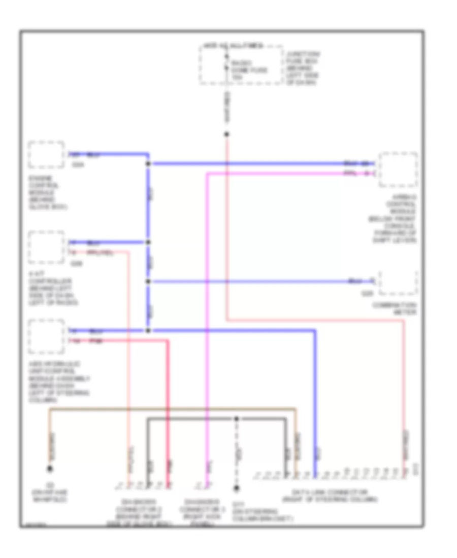
Электросхема компьютерной линии передачи данных CAN для Suzuki Aerio GS 2002
Электросхема компьютерной линии передачи данных CAN для Suzuki Aerio GS 2002 - Список элементов:
СИСТЕМА КОНДИЦИОНЕРА СИСТЕМА ОХЛАЖДЕНИЯ СИСТЕМА ПЕРЕДАЧИ ДАННЫХ СИСТЕМА КРУИЗКОНТРОЛЯ СИСТЕМА АНТИБЛОКИРОВОЧНОЙ ТОРМОЗНОЙ СИСТЕМЫ СИСТЕМА УПРАВЛЕНИЯ ДВИГАТЕЛЯ ПОДОГРЕВ СТЕКОЛ И ЗЕРКАЛ ЗАЗЕМЛЕНИЕ ПОДКЛЮЧЕНИЕ МАССЫ ВНУТРЕННЕЕ ОСВЕЩЕНИЕ ВНЕШНЕЕ ОСВЕЩЕНИЕ ЗВУКОВОЙ СИГНАЛ ГУДОК СИСТЕМА ФАР ПРИБОРНАЯ ПАНЕЛЬ СИСТЕМА ПРИВОДА ПРИВОД СТЕКЛОПОДЪЕМНИКОВ ПОДУШКИ БЕЗОПАСНОСТИ ЦЕНТРАЛЬНЫЙ ЗАМОК БЛОК ПРЕДОХРАНИТЕЛЕЙ И РЕЛЕ МАГНИТОЛА МУЛЬТИМЕДИЯ ПРЕДУПРЕЖДАЮЩИЕ СИСТЕМЫ СТАРТЕР ГЕНЕРАТОР ПРИВОД ЗЕРКАЛ БЛОКИРОВКИ СЕЛЕКТОРА СТОЯНОЧНЫЙ ТОРМОЗ СТЕКЛООЧИСТИТЕЛИ И СТЕКЛООМЫВАТЕЛИ ДВОРНИКИ