СИСТЕМА ПЕРЕДАЧИ ДАННЫХ
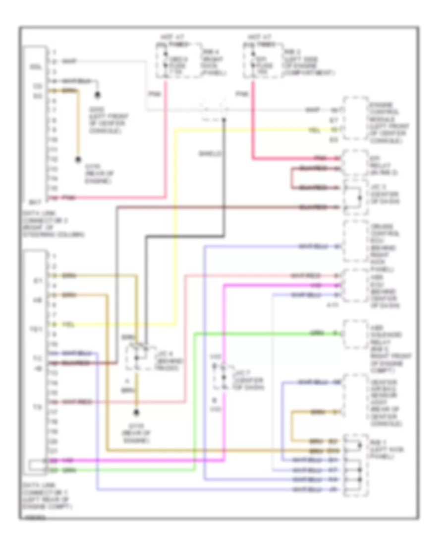
Электросхема компьютерной линии передачи данных CAN для Toyota Celica GT 1998
Электросхема компьютерной линии передачи данных CAN для Toyota Celica GT 1998 - Список элементов:
 English
Электросхема компьютерной линии передачи данных CAN для Toyota Celica GT 1998
Электросхема компьютерной линии передачи данных CAN для Toyota Celica GT 1998 - Список элементов: