СИСТЕМА ПЕРЕДАЧИ ДАННЫХ
Электросхема компьютерной линии передачи данных CAN для Volvo V70 2000
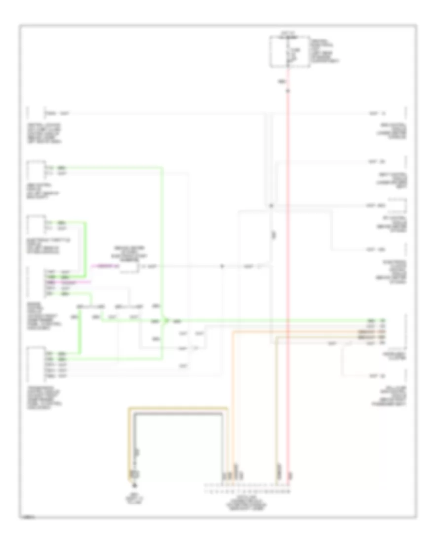
Электросхема компьютерной линии передачи данных CAN для Volvo V70 2000 - Список элементов:
- (behind center of dash) electronic start inhibitor
- A/t
- A19
- A20
- A30
- A37
- A55
- Abs control module (on left rear of eng compt)
- B13
- B14
- B19
- B22
- Central electrical unit (left rear of engine compartment)
- Central locking/ anti-theft alarm control module (behind lower left end of dash)
- Data link connector (dlc) (on center console, near shift lever)
- Electronic climate control module (behind center of dash)
- Electronic throttle module (on left rear of intake manifold)
- Engine control module (on right front inner fender panel, in control module box)
- Fuse c5 15a
- G901 (right "a" pillar)
- Hot at all times
- Instrument cluster
- M/t
- Red
- Roll-over bar control module (behind right passenger seat)
- Rti control module (behind center of dash)
- Seat control module (under driver's seat)
- Srs control module (under center console)
- Transmission control module (on right front inner fender panel, in control module box)
 Русский
 English