СИСТЕМА ПЕРЕДАЧИ ДАННЫХ
Электросхема компьютерной линии передачи данных CAN для Volvo V70 GT 1998
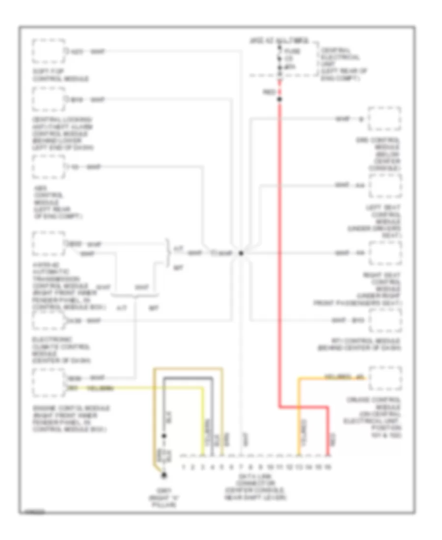
Электросхема компьютерной линии передачи данных CAN для Volvo V70 GT 1998 - Список элементов:
- A/t
- A23
- A30
- Abs control module (left rear of eng compt)
- Aw50-42 automatic transmission control module (right front inner fender panel, in control module box)
- B13
- B19
- B22
- B36
- Central electrical unit (left rear of eng compt)
- Central locking/ anti-theft alarm control module (behind lower left end of dash)
- Cruise control module (on central electrical unit, position 101 & 102)
- Data link connector (center console, near shift lever)
- Electronic climate control module (center of dash)
- Engine contol module (right front inner fender panel, in control module box)
- Fuse c5 15a
- G901 (right "a" pillar)
- Hot at all times
- Left seat control module (under driver's seat)
- M/t
- Red
- Right seat control module (under right front passenger's seat)
- Rti control module (behind center of dash)
- Soft-top control module
- Srs control module (below center console)
 English