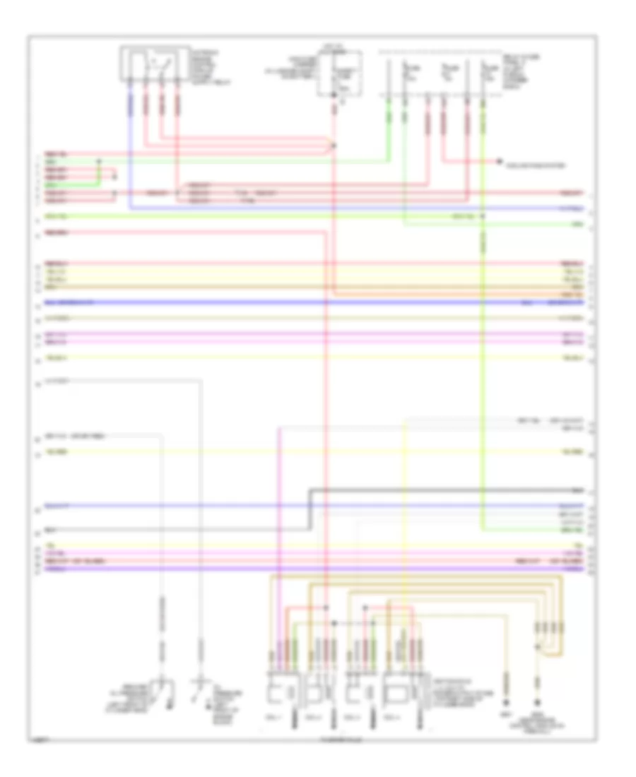
СИСТЕМА УПРАВЛЕНИЯ ДВИГАТЕЛЯ
2.0L ТУРБО
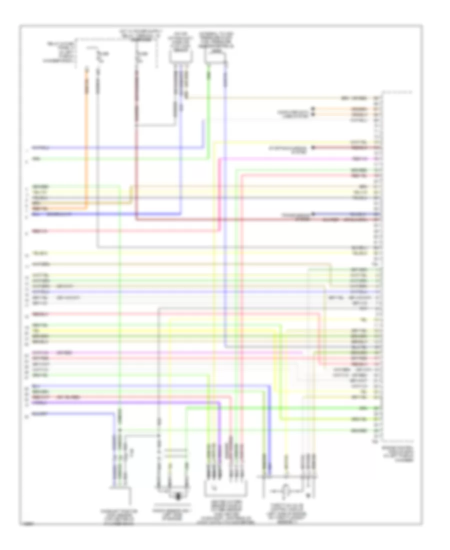
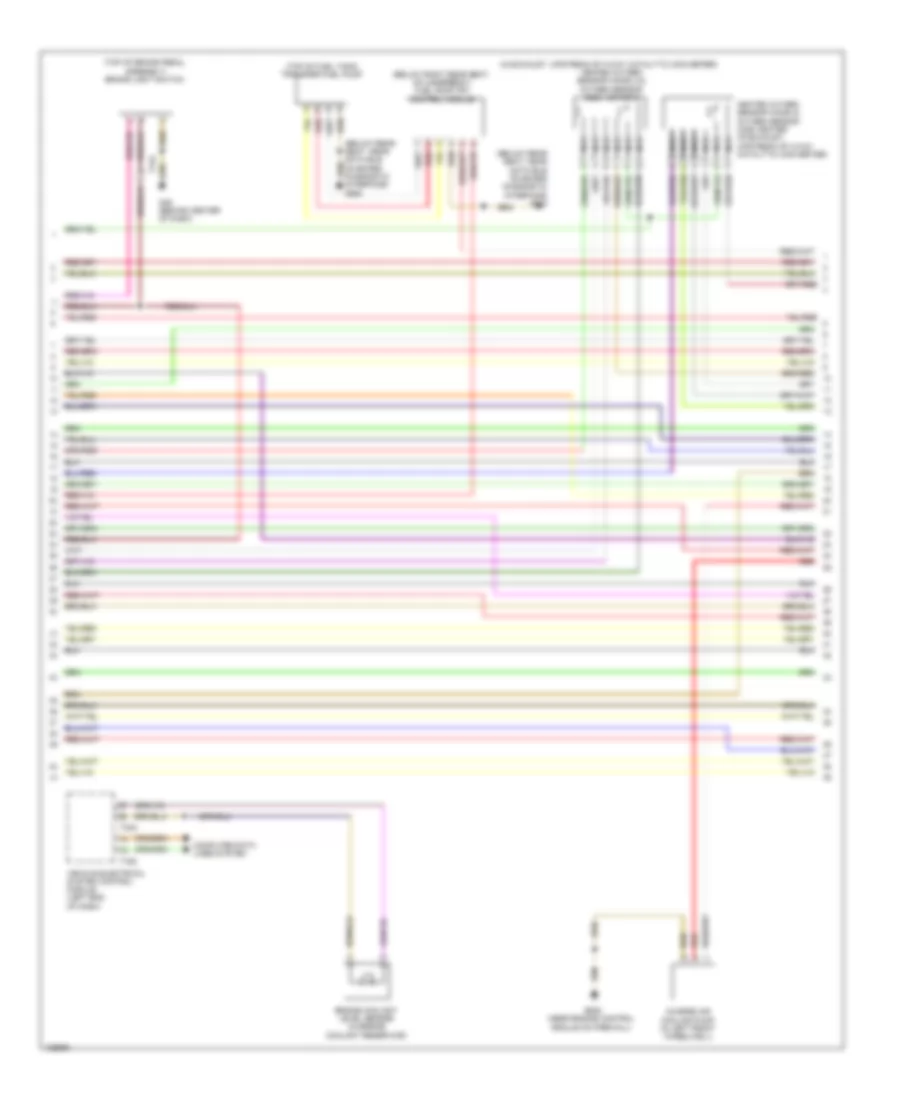
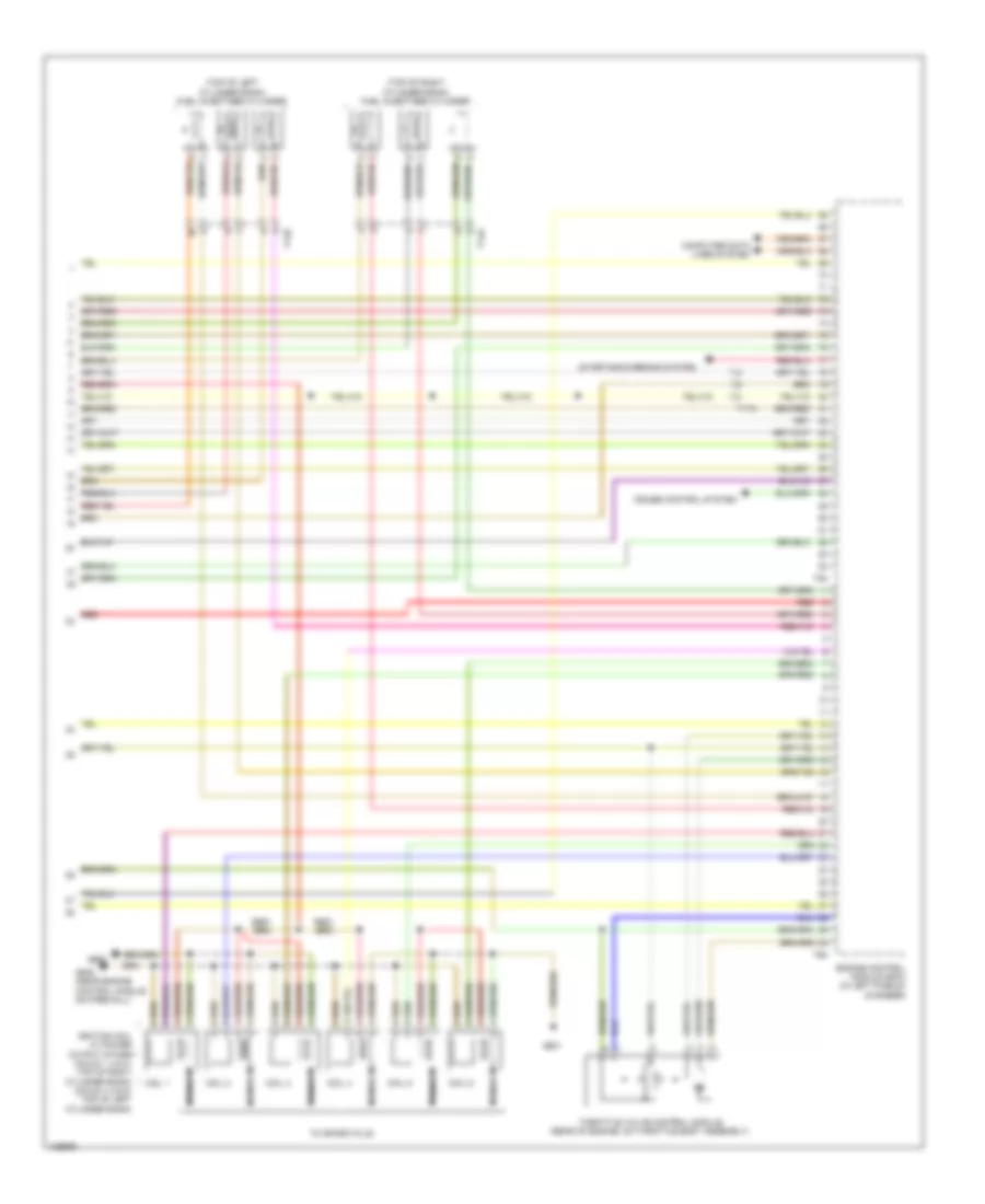
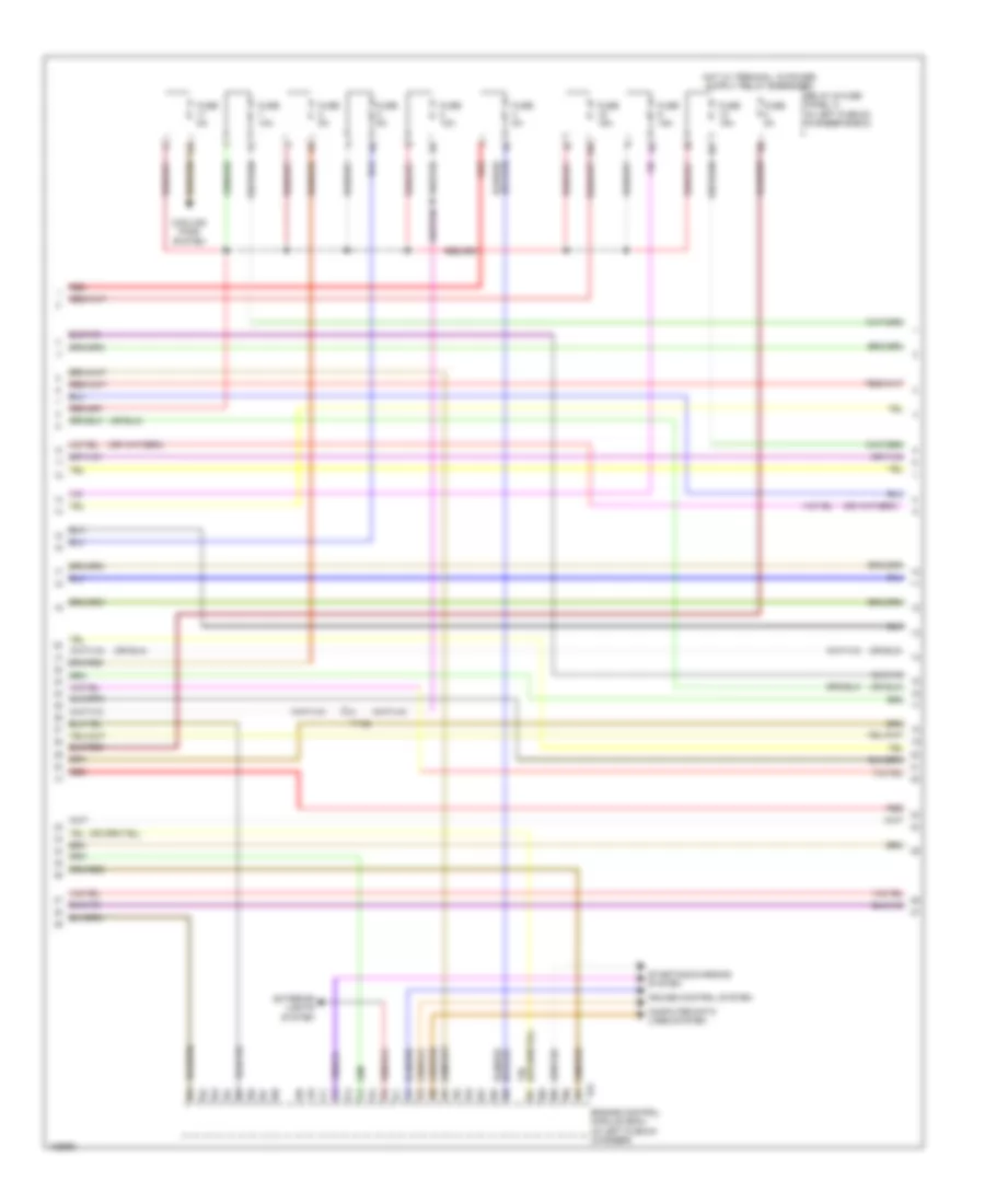
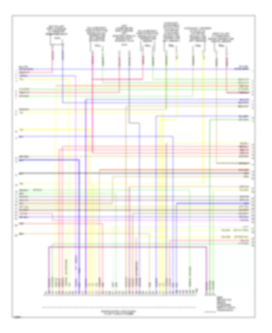
2.0L турбо, Электросхема системы управления двигателем (1 из 6) для Audi A6 Quattro Premium Plus 2014


2.0L турбо, Электросхема системы управления двигателем (1 из 6) для Audi A6 Quattro Premium Plus 2014 - Список элементов:
- (right side of luggage compt) comfort system central control module
- 14a
- Accelerator pedal position sensor & accelerator pedal position sensor 2 (top of accelerator pedal assembly)
- Cooling fans system
- Engine control module (ecm) (in left plenum chamber)
- Fuse 15a
- Fuse 20a
- Fuse 5a
- G645 (near engine control module on firewall)
- Heater for oxygen sensor 1 after catalytic converter & oxygen sensor after three way catalytic converter (in exhaust, downstream of 3-way catalytic converter)
- Nca
- Oil level thermal sensor (bottom of engine oil pan)
- Relay & fuse panel a (in left plenum chamber e-box)
- Starting/ charging system
- Steering column electronic systems control module (top of steering column)
- System
- T16e
- T17a
- T17b
- T17h
- T17i
- T17o
- T32g
- T94
- Transmissions
- Transmissions system
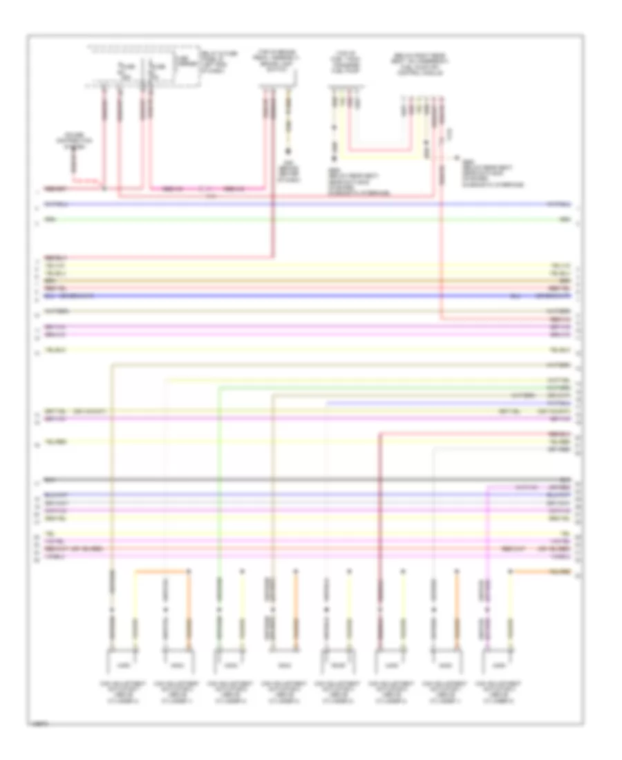
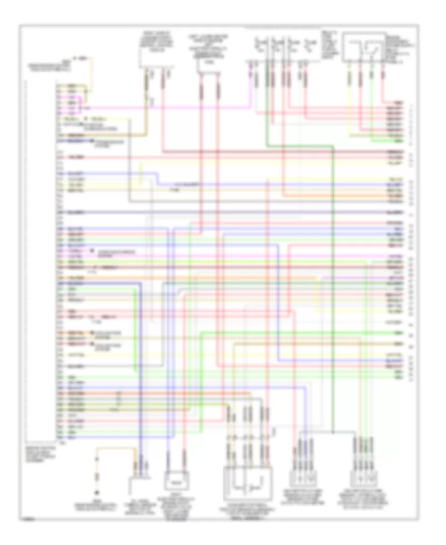
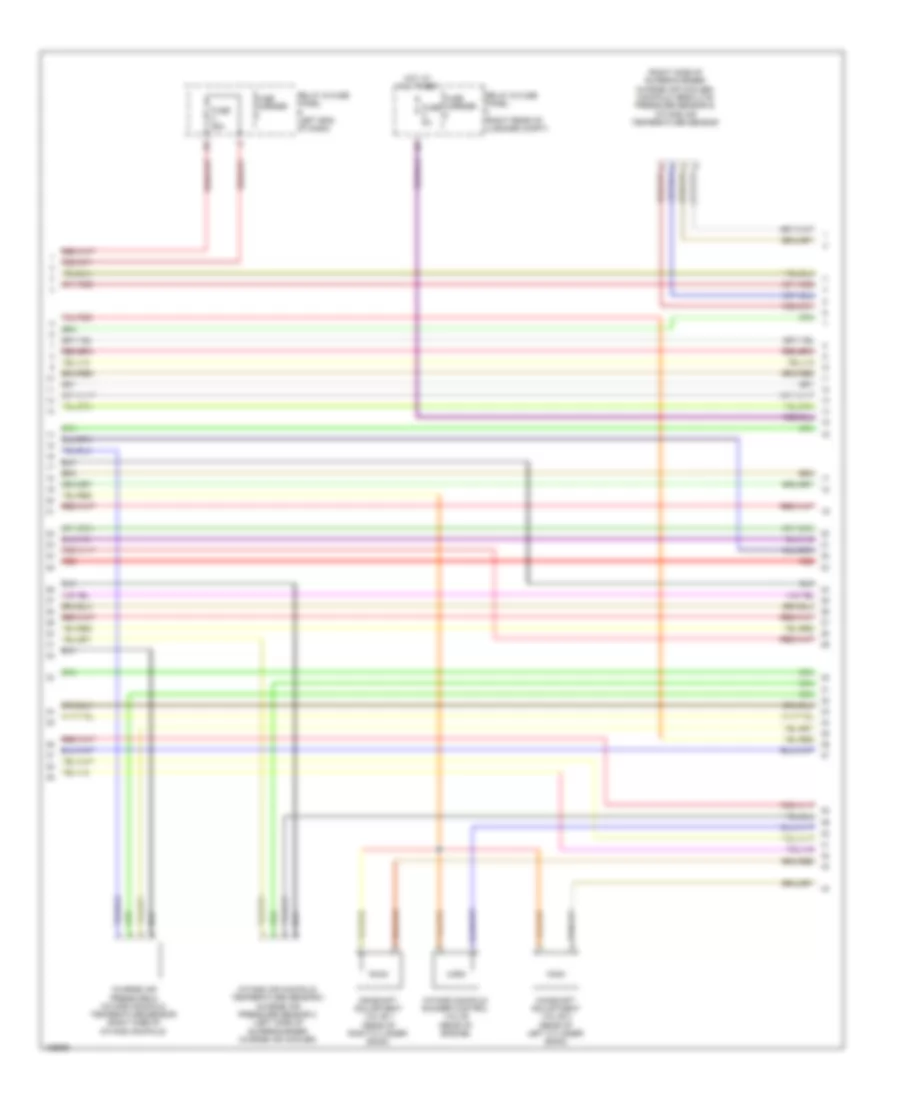
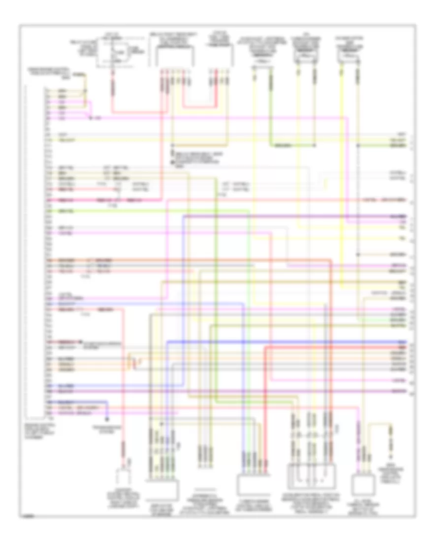
2.0L турбо, Электросхема системы управления двигателем (2 из 6) для Audi A6 Quattro Premium Plus 2014
2.0L турбо, Электросхема системы управления двигателем (2 из 6) для Audi A6 Quattro Premium Plus 2014 - Список элементов:
- 10a
- 11a
- Coil 1
- Coil 2
- Coil 3
- Coil 4
- Cooling fans system
- Fuse 10a
- Fuse 15a
- Fuse 5a
- G601
- G645 (near engine control module on firewall)
- Hot at all times
- Ignition coils 1, 2, 3 & 4 w/ power output stage (top right side of cylinder bank)
- Main fuse carrier (in luggage compt on battery)
- Nca
- Oil pressure switch (left front of engine block)
- Red
- Reduced oil pressure switch (left front of cylinder head)
- Relay & fuse panel a (in left plenum chamber e-box)
- Safety fuse 150a
- T17b
- To spark plug
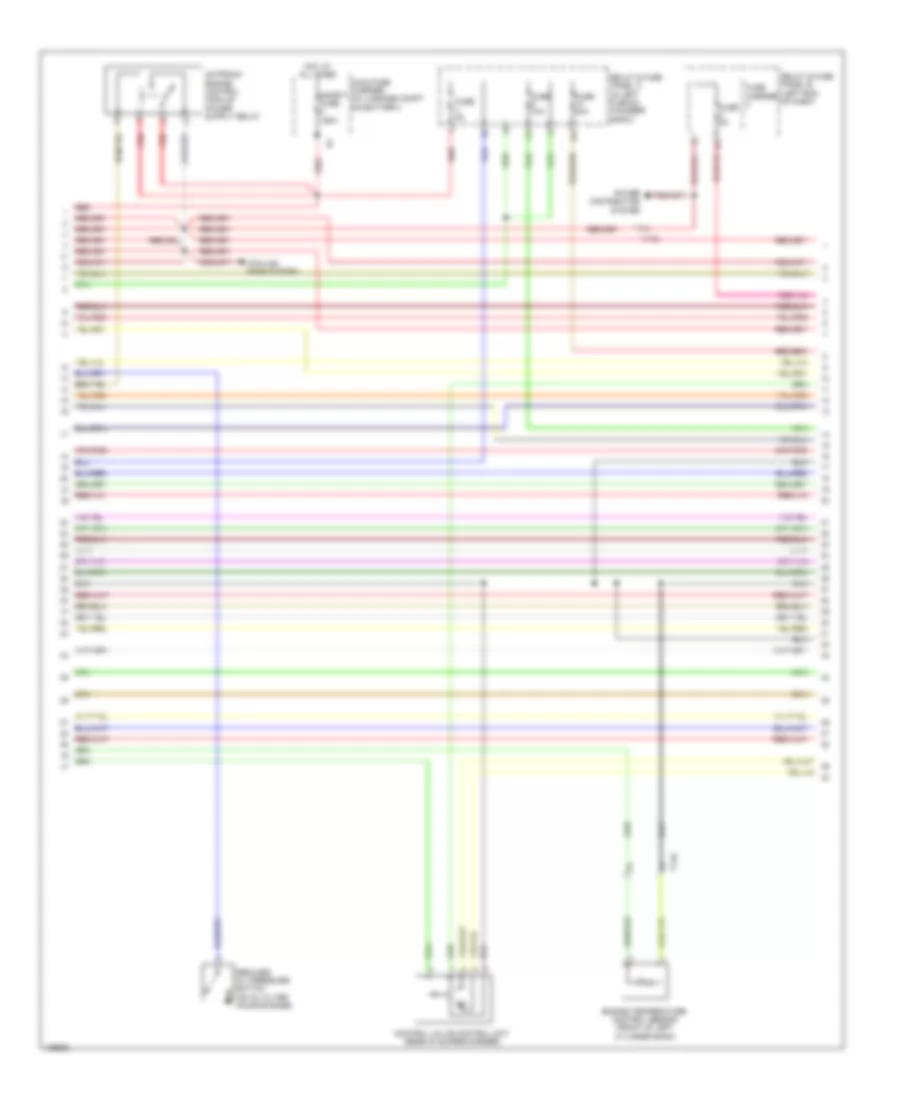
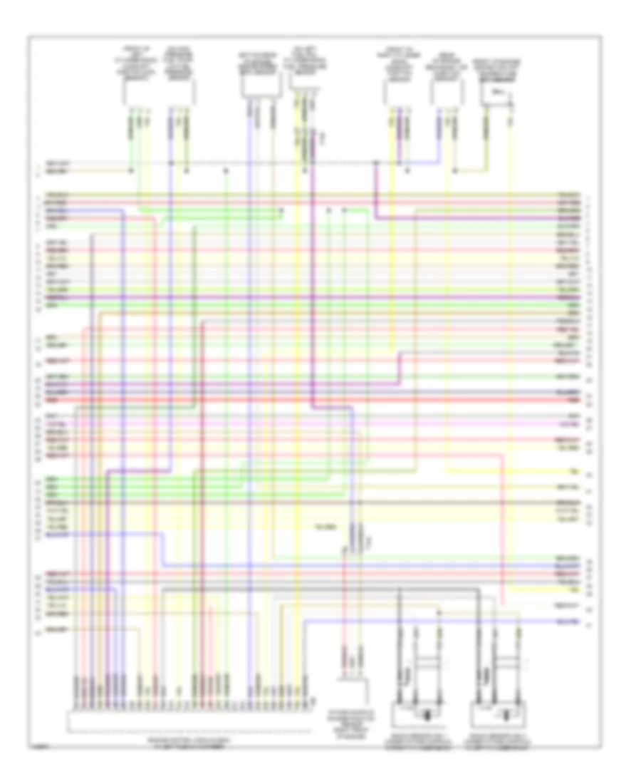
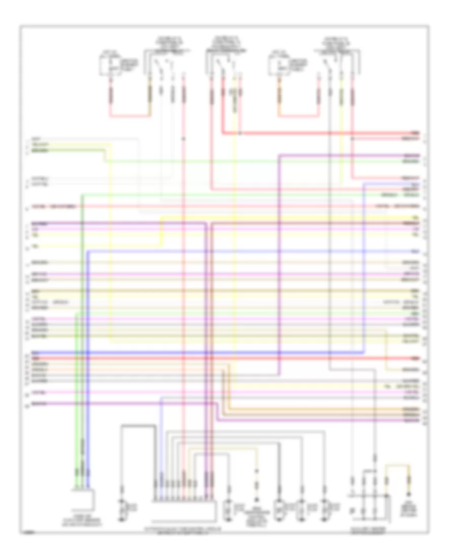
2.0L турбо, Электросхема системы управления двигателем (3 из 6) для Audi A6 Quattro Premium Plus 2014
2.0L турбо, Электросхема системы управления двигателем (3 из 6) для Audi A6 Quattro Premium Plus 2014 - Список элементов:
- (below right rear seat, on underbody) fuel pump (fp) control module
- (or red)
- (top of brake pedal assembly) brake lamp switch
- (top of fuel tank) transfer fuel pump
- Cam adjustment actuator 1 (above cylinder 1)
- Cam adjustment actuator 2 (above cylinder 1)
- Cam adjustment actuator 3 (above cylinder 2)
- Cam adjustment actuator 4 (above cylinder 2)
- Cam adjustment actuator 5 (above cylinder 3)
- Cam adjustment actuator 6 (above cylinder 3)
- Cam adjustment actuator 7 (above cylinder 4)
- Cam adjustment actuator 8 (above cylinder 4)
- Fuse 25a
- Fuse 5a
- Fuse carrier
- G45 (behind center of dash)
- G688 (below rear seat, near data bus on board diagnostic interface)
- Power distribution system
- Red
- Relay & fuse panel b (left end of dash)
- T17b
- T17i
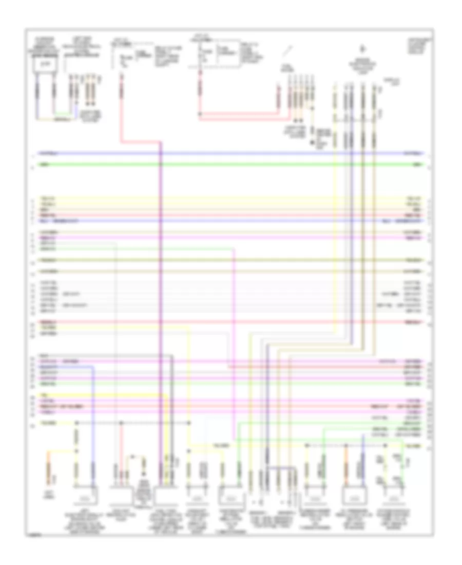
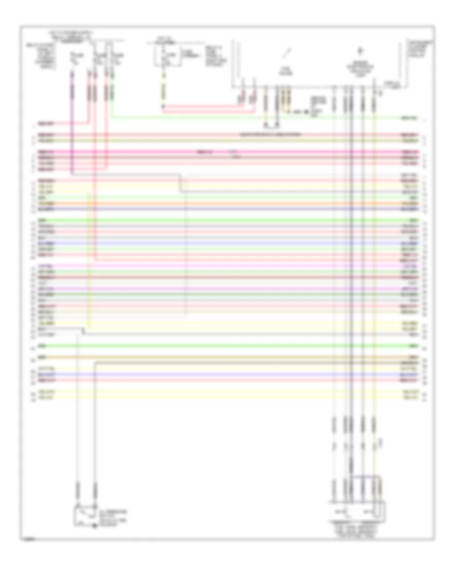
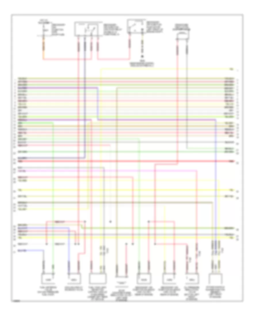
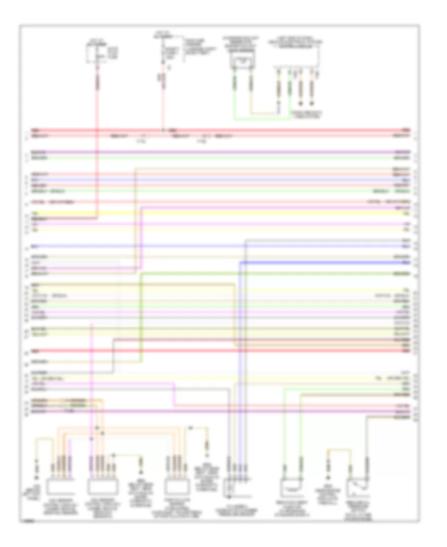
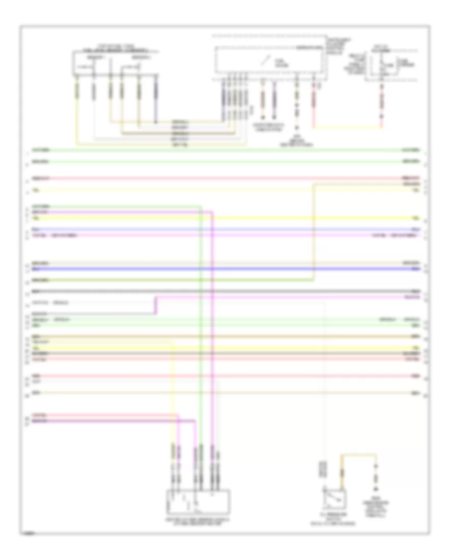
2.0L турбо, Электросхема системы управления двигателем (4 из 6) для Audi A6 Quattro Premium Plus 2014
2.0L турбо, Электросхема системы управления двигателем (4 из 6) для Audi A6 Quattro Premium Plus 2014 - Список элементов:
- (behind center of dash) g45
- (in engine coolant reservoir) engine coolant level sensor
- (left end of dash) vehicle electrical system control module
- (not used)
- (or red)
- Camshaft adjustment valve 1 (front of cylinder bank)
- Computer data lines system
- Coolant recirculation pump
- Display unit
- Engine electronics indicator lamp
- Fuel gauge
- Fuel level sensor & fuel level sensor 2 (top of fuel tank)
- Fuel tank leak detection control module (if equipped) (under left rear of vehicle)
- Fuse 5a
- Fuse carrier
- Fuse carrier 1
- G645 (near engine control module on firewall)
- Hot at all times
- Instrument cluster control module
- Intake manifold runner control (imrc) valve (left rear of engine)
- Left electrohydraulic engine mount solenoid valve (left lower center side of engine)
- Oil pressure regulation valve (bottom left front of engine)
- Red
- Relay & fuse panel c (right end of dash)
- Relay & fuse panel f (right rear of luggage compt)
- Sensor 1
- Sensor 2
- T14b
- T16c
- T17b
- T17h
- T32
- T32a
- Turbocharger recirculation valve (on turbocharger)
- Wastegate bypass regulator valve (on turbocharger)
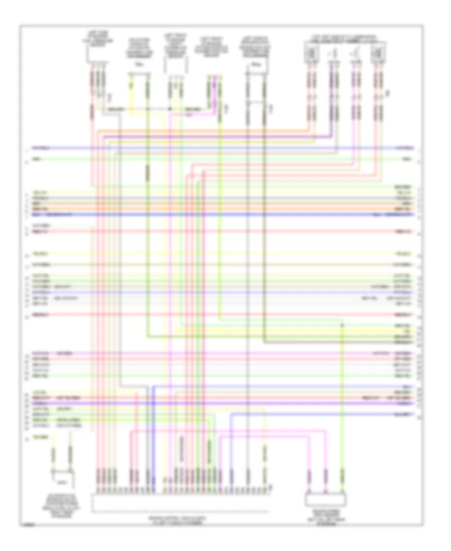
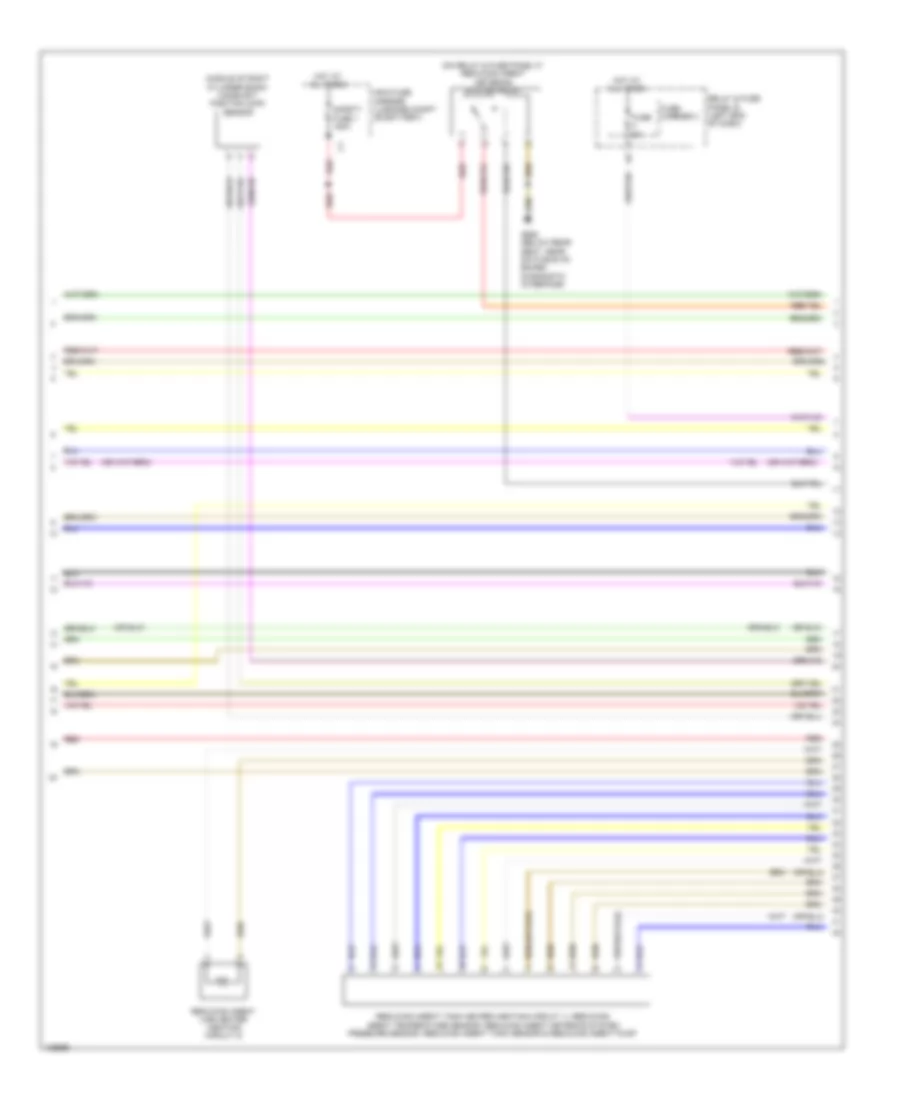
2.0L турбо, Электросхема системы управления двигателем (5 из 6) для Audi A6 Quattro Premium Plus 2014
2.0L турбо, Электросхема системы управления двигателем (5 из 6) для Audi A6 Quattro Premium Plus 2014 - Список элементов:
- (left front of engine compt) charge air pressure sensor
- (left front of engine) intake manifold runner position sensor
- (left side of engine block)
- (left side of engine) fuel pressure sensor
- (on intake manifold) intake air temperature (iat) sensor
- (or red)
- (top left side of cylinder bank) fuel injector cylinders 1, 2, 3 & 4
- Engine control module (ecm) (in left plenum chamber)
- Engine coolant temperature (ect) sensor
- Engine speed (rpm) sensor (bottom left rear of engine)
- Evaporative emission (evap) canister purge regulator valve 1 (right rear of engine)
- T14b
- T60
- T8s
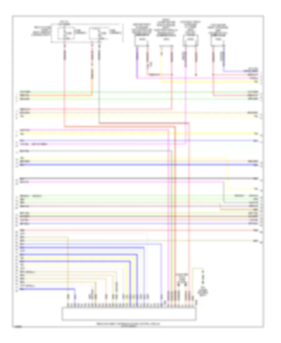
2.0L турбо, Электросхема системы управления двигателем (6 из 6) для Audi A6 Quattro Premium Plus 2014
2.0L турбо, Электросхема системы управления двигателем (6 из 6) для Audi A6 Quattro Premium Plus 2014 - Список элементов:
- (integral to high pressure pump) fuel pressure regulator valve
- (on air intake duct) mass air flow (maf) sensor
- (or red)
- Camshaft position (cmp) sensor (top center of cylinder bank)
- Computer data lines system
- Engine control module (ecm) (in left plenum chamber)
- Fuse 5a
- Heated oxygen sensor (ho2s) & oxygen sensor (o2s) heater (in exhaust, upstream of 3-way catalytic converter)
- Knock sensor (ks) 1 (left side of engine)
- Nca
- Relay & fuse panel a (in left plenum chamber e-box)
- Starting/charging system
- T14b
- T60
- T94
- Throttle valve control module (left side of engine, on throttle body assembly)
- Transmissions system
3.0L SC
3.0L SC, Электросхема системы управления двигателем (1 из 8) для Audi A6 Quattro Premium Plus 2014
3.0L SC, Электросхема системы управления двигателем (1 из 8) для Audi A6 Quattro Premium Plus 2014 - Список элементов:
- (left lower center side of engine) left electrohydraulic engine mount solenoid valve
- (right side of luggage compt) comfort system central control module
- 17a
- Accelerator pedal position sensor & sensor 2 (top of accelerator pedal assembly)
- Cooling fans system
- Engine control module (ecm) (in left plenum chamber)
- Fuse 15a
- Fuse 5a
- G645 (near engine control module on firewall)
- Heater for oxygen sensor 1 after & 3 way catalytic converter (in exhaust, downstream of 3-way catalytic)
- Heater for oxygen sensor 2 & oxygen sensor 2 after catalytic converter
- Nca
- Oil level thermal sensor (bottom of engine oil pan)
- Red
- Relay & fuse panel a (in left plenum chamber e-box)
- Right electrohydraulic engine mount solenoid valve (right lower center side of engine)
- Starting/ charging system
- Starting/charging system
- T14b
- T17a
- T17b
- T17h
- T32g
- T94
- Transmissions system
3.0L SC, Электросхема системы управления двигателем (2 из 8) для Audi A6 Quattro Premium Plus 2014
3.0L SC, Электросхема системы управления двигателем (2 из 8) для Audi A6 Quattro Premium Plus 2014 - Список элементов:
- 14a
- Control valve control unit (rear of supercharger)
- Cooling fans system
- Engine temperature control sensor (front of left cylinder bank)
- Fuse 10a
- Fuse 20a
- Fuse 5a
- Fuse carrier
- Hot at all times
- Main fuse carrier (in luggage compt on battery)
- Power distribution system
- Red
- Reduced oil pressure switch (on oil filter housing base)
- Relay & fuse panel a (in left plenum chamber e-box)
- Relay & fuse panel b (left end of dash)
- Safety fuse 150a
- T14a
- T17b
3.0L SC, Электросхема системы управления двигателем (3 из 8) для Audi A6 Quattro Premium Plus 2014
3.0L SC, Электросхема системы управления двигателем (3 из 8) для Audi A6 Quattro Premium Plus 2014 - Список элементов:
- (behind center of dash) g45
- 10a
- 16a
- Computer data lines system
- Display unit
- Engine electronics indicator lamp
- Fuel gauge
- Fuel level sensor & fuel level sensor 2 (top of fuel tank)
- Fuse 15a
- Fuse 5a
- Fuse carrier 1
- Hot at all times
- Instrument cluster control module
- Oil pressure switch (on oil filter housing)
- Relay & fuse panel a (in left plenum chamber e-box)
- Relay & fuse panel c (right end of dash)
- Sensor 1
- Sensor 2
- T17h
- T17i
- T32
3.0L SC, Электросхема системы управления двигателем (4 из 8) для Audi A6 Quattro Premium Plus 2014
3.0L SC, Электросхема системы управления двигателем (4 из 8) для Audi A6 Quattro Premium Plus 2014 - Список элементов:
- (below rear seat, near data bus on board diagnostic interface) g688
- (below right rear seat, on underbody) fuel pump (fp) control module
- (in exhaust, upstream of 3-way catalytic converter) heated oxygen sensor (ho2s) 2 & oxygen sensor (o2s) heater 2
- (top of brake pedal assembly) brake light switch
- (top of fuel tank) transfer fuel pump
- Charge air cooling pump (in left front wheelwell)
- Computer data lines system
- Engine coolant level sensor (in engine coolant reservoir)
- G45 (behind center of dash)
- G645 (near engine control module on firewall)
- Heated oxygen sensor (ho2s) & oxygen sensor (o2s) heater (in exhaust, upstream of 3-way catalytic converter)
- Nca
- Red
- T16c
- T17o
- T32a
- Vehicle electrical system control module (left end of dash)
3.0L SC, Электросхема системы управления двигателем (5 из 8) для Audi A6 Quattro Premium Plus 2014
3.0L SC, Электросхема системы управления двигателем (5 из 8) для Audi A6 Quattro Premium Plus 2014 - Список элементов:
- (right side of supercharger charge air cooler) manifold absolute pressure sensor & intake air temperature sensor
- Camshaft adjustment valve 1 (rear of right cylinder bank)
- Camshaft adjustment valve 2 (rear of left cylinder bank)
- Charge air pressure & intake manifold temperature sensor (right side of intake manifold)
- Fuse 25a
- Fuse 5a
- Fuse carrier
- Hot at all times
- Intake air manifold temperature sensor 2 charge air pressure sensor 2 (left side of supercharger charge air cooler)
- Intake manifold runner control valve (rear of engine)
- Red
- Relay & fuse panel b (left end of dash)
- Relay & fuse panel f (right rear of luggage compt)
3.0L SC, Электросхема системы управления двигателем (6 из 8) для Audi A6 Quattro Premium Plus 2014
3.0L SC, Электросхема системы управления двигателем (6 из 8) для Audi A6 Quattro Premium Plus 2014 - Список элементов:
- (bottom rear of engine) engine speed (rpm) sensor
- (front of engine) engine coolant temperature (ect) sensor
- (front of left cylinder bank) camshaft position (cmp) sensor 2
- (front of right cylinder bank) camshaft position sensor
- (on high pressure fuel pump) low fuel pressure sensor
- (on left fuel rail cylinder bank) fuel pressure sensor
- (rear of engine) secondary air injection sensor 1
- Engine control module (ecm) (in left plenum chamber)
- Intake manifold runner position sensor (right front of engine)
- Knock sensor (ks) 1 (under intake manifold, in right cylinder bank)
- Knock sensor (ks) 2 (under intake manifold, in left cylinder bank)
- Nca
- Red
- T14a
- T14b
- T60
3.0L SC, Электросхема системы управления двигателем (7 из 8) для Audi A6 Quattro Premium Plus 2014
3.0L SC, Электросхема системы управления двигателем (7 из 8) для Audi A6 Quattro Premium Plus 2014 - Список элементов:
- 50a
- Cooling circuit solenoid valve
- Crankcase ventilation shut-off valve
- Evap canister purge regulator valve 1 (left side of engine)
- Fuel metering valve (on high pressure fuel pump)
- Fuel tank leak detection control module (if equipped) (under left rear of vehicle)
- G645 (near engine control module on firewall)
- Hot at all times
- Intake manifold runner position sensor 2 (left front of engine)
- Oil pressure regulation valve (bottom left front of engine)
- Red
- Secondary air injection (air) pump fuse
- Secondary air injection (air) pump relay (on relay & fuse panel a)
- Secondary air injection pump motor (left front of engine compt)
- Secondary air injection solenoid (air) valve (rear of engine)
- Secondary air injection solenoid (air) valve 2 (rear of engine)
- T14a
- T14b
- T17b
3.0L SC, Электросхема системы управления двигателем (8 из 8) для Audi A6 Quattro Premium Plus 2014
3.0L SC, Электросхема системы управления двигателем (8 из 8) для Audi A6 Quattro Premium Plus 2014 - Список элементов:
- (top of left cylinder bank) fuel injectors cylinder
- (top of right cylinder bank) fuel injectors cylinder
- Coil 1
- Coil 2
- Coil 3
- Coil 4
- Coil 5
- Coil 6
- Computer data lines system
- Cruise control system
- Engine control module (ecm) (in left plenum chamber)
- G600
- G601
- G645 (near engine control module on firewall)
- Ignition coil w/ power output stage (coils 1, 2 & 3: top of right cylinder bank) (coils 4, 5 & 6: top of left cylinder bank)
- Nca
- Red
- Starting/charging system
- T14a
- T14b
- T17a
- T60
- T94
- Throttle valve control module (rear of engine, on throttle body assembly)
- To spark plug
3.0L ТУРБО ДИЗЕЛЬ
3.0L турбо дизель, Электросхема системы управления двигателем (1 из 9) для Audi A6 Quattro Premium Plus 2014
3.0L турбо дизель, Электросхема системы управления двигателем (1 из 9) для Audi A6 Quattro Premium Plus 2014 - Список элементов:
- (below rear seat, near data bus on board diagnostic interface) g688
- (below right rear seat, on underbody) fuel pump (fp) control module
- (in exhaust, upstream of catalytic converter) exhaust gas temperature sensor 3
- (near engine control module on firewall) g645
- (on egr motor) egr temperature sensor
- (on turbocharger) exhaust gas temperature sensor 1
- (top of fuel tank) transfer fuel pump
- Accelerator pedal position sensor & accelerator pedal position sensor 2 (top of accelerator pedal assembly)
- Comfort system central control module (right side of luggage compt)
- Differential pressure sensor (if equipped) (in exhaust, upstream of catalytic converter)
- Egr motor (top center of engine)
- Engine control module (ecm) (in left plenum chamber)
- Fuse 25a
- Fuse carrier
- G645 (near engine control module on firewall)
- Hot at all times
- Oil level thermal sensor (bottom of engine oil pan)
- Red
- Relay & fuse panel b (left end of dash)
- Starting/charging system
- T10l
- T17a
- T17b
- T17g
- T17h
- T32g
- T91
- Transmissions system
- Turbocharger control module 1 (on turbocharger)
3.0L турбо дизель, Электросхема системы управления двигателем (2 из 9) для Audi A6 Quattro Premium Plus 2014
3.0L турбо дизель, Электросхема системы управления двигателем (2 из 9) для Audi A6 Quattro Premium Plus 2014 - Список элементов:
- (on relay & fuse panel b) high heat output relay
- (on relay & fuse panel b) low heat output relay
- 40a
- 60a
- Automatic glow time control module (on relay & fuse panel a)
- Auxiliary heater heating element
- G45 (behind center of dash)
- G645 (near engine control module on firewall)
- Glow plug
- Heating element fuse 1
- Heating element fuse 2
- Hot at all times
- Mass air flow (maf) sensor (on air intake duct)
- Red
3.0L турбо дизель, Электросхема системы управления двигателем (3 из 9) для Audi A6 Quattro Premium Plus 2014
3.0L турбо дизель, Электросхема системы управления двигателем (3 из 9) для Audi A6 Quattro Premium Plus 2014 - Список элементов:
- (in engine coolant reservoir) engine coolant level sensor
- (left end of dash) vehicle electrical system control module
- 80a
- Computer data lines system
- Cylinder 2 combustion chamber pressure sensor
- G44 (behind left kick panel)
- G645 (near engine control module on firewall)
- G688 (below rear seat, near data bus on board diagnostic interface)
- Glow plug fuse
- Hot at all times
- Injector (w/ emissions standard euro 4)
- Main fuse carrier (luggage compt on battery)
- Nox sensor control module 1 (under vehicle, near nox sensor)
- Nox sensor control module 2 (under vehicle, near nox sensor 2)
- Particulate sensor (if equipped) (in exhaust, downstream of particulate filter)
- Red
- Reduced oil pressure switch (on oil filter housing base)
- Reducing agent
- Safety fuse 3 150a
- T16c
- T17b
- T17g
- T32a
3.0L турбо дизель, Электросхема системы управления двигателем (4 из 9) для Audi A6 Quattro Premium Plus 2014
3.0L турбо дизель, Электросхема системы управления двигателем (4 из 9) для Audi A6 Quattro Premium Plus 2014 - Список элементов:
- 10a
- 11a
- 16a
- Computer data lines system
- Cooling fans system
- Cruise control system
- Engine control module (ecm) (in left plenum chamber)
- Exterior lights system
- Fuse 10a
- Fuse 15a
- Fuse 5a
- Red
- Relay & fuse panel a (in left plenum chamber e-box)
- Starting/charging system
- T17b
- T91
3.0L турбо дизель, Электросхема системы управления двигателем (5 из 9) для Audi A6 Quattro Premium Plus 2014
3.0L турбо дизель, Электросхема системы управления двигателем (5 из 9) для Audi A6 Quattro Premium Plus 2014 - Список элементов:
- (top of fuel tank) fuel level sensor 1 & sensor 2
- Computer data lines system
- Display unit
- Fuel gauge
- Fuse 5a
- Fuse carrier
- G45 (behind center of dash)
- G645 (near engine control module on firewall)
- Heated oxygen sensor (ho2s) & oxygen sensor heater
- Hot at all times
- Instrument cluster control module
- Nca
- Oil pressure
- Red
- Relay & fuse panel c (right end of dash)
- Sensor 1
- Sensor 2
- Switch (on oil filter housing)
- T17h
- T32
3.0L турбо дизель, Электросхема системы управления двигателем (6 из 9) для Audi A6 Quattro Premium Plus 2014
3.0L турбо дизель, Электросхема системы управления двигателем (6 из 9) для Audi A6 Quattro Premium Plus 2014 - Список элементов:
- (middle of right cylinder bank) camshaft position (cmp) sensor
- (on relay & fuse panel f) reducing agent metering system relay
- Fuse 5a
- Fuse carrier 3
- G688 (below rear seat, near data bus on board diagnostic interface)
- Hot at all times
- Main fuse carrier (luggage compt on battery)
- Red
- Reducing agent line heater (heating circuit 2)
- Reducing agent tank heater (heating circuit 1), reducing agent temperature sensor, reducing agent metering system pressure sensor, reducing agent tank sensor & reducing agent pump
- Relay & fuse panel b (left end of dash)
- Safety fuse 1 150a
3.0L турбо дизель, Электросхема системы управления двигателем (7 из 9) для Audi A6 Quattro Premium Plus 2014
3.0L турбо дизель, Электросхема системы управления двигателем (7 из 9) для Audi A6 Quattro Premium Plus 2014 - Список элементов:
- (center front of engine) map controlled engine cooling thermostat
- (right lower center side of engine) right electrohydraulic engine mount solenoid valve
- (top center front of engine) egr cooler switch over valve
- (top right front of engine) cylinder head coolant valve
- Computer data lines system
- Fuse 15a
- Fuse 30a
- Fuse carrier 3
- Fuse carrier 5
- G34 (under driver's seat)
- Hot at all times
- Red
- Reducing agent metering system control module (if equipped)
- Relay & fuse panel f (right rear of luggage compt)
- T10l
- T28a
- T8an
3.0L турбо дизель, Электросхема системы управления двигателем (8 из 9) для Audi A6 Quattro Premium Plus 2014
3.0L турбо дизель, Электросхема системы управления двигателем (8 из 9) для Audi A6 Quattro Premium Plus 2014 - Список элементов:
- (bottom left front of engine) oil pressure regulation valve
- (front of left cylinder bank) engine temperature control sensor
- (in exhaust, downstream of catalytic converter) (if equipped) exhaust gas temperature (ect) sensor 4
- (in exhaust, upstream of catalytic converter) exhaust gas temperature (ect) sensor 2
- (left lower center side of engine) left electrohydraulic engine mount solenoid valve
- (on lower right hose on radiator) engine coolant temperature (ect) sensor (on radiator)
- (on lower right hose on radiator) engine coolant temperature sensor
- Engine control module (ecm) (in left plenum chamber)
- Gear recognition sensor (if equipped) (rear of manual transmission)
- Red
- T105
- T10l
3.0L турбо дизель, Электросхема системы управления двигателем (9 из 9) для Audi A6 Quattro Premium Plus 2014
3.0L турбо дизель, Электросхема системы управления двигателем (9 из 9) для Audi A6 Quattro Premium Plus 2014 - Список элементов:
- (integral to high pressure pump) fuel metering valve
- (on high pressure fuel pump) fuel pressure regulator valve
- (or red)
- (top of engine) fuel temperature sensor
- Charge air pressure sensor & intake air temperature (iat) sensor (left front of engine compt)
- Coolant fan control module (if equipped) (on left coolant fan motor)
- Coolant fan control module 2 (if equipped) (on right coolant fan motor)
- Engine control module (ecm) (in left plenum chamber)
- Engine speed (rpm) sensor (bottom rear of engine)
- Fuel injector cylinders
- Fuel pressure sensor (on left cylinder bank fuel rail)
- Intake flap motor (top center front of engine)
- Nca
- Oil temperature sensor 2 (front of engine)
- T105
- T10l
- Throttle valve control module (left front of engine, on throttle body assembly)
- Transmissions system

 English