СИСТЕМА УПРАВЛЕНИЯ ДВИГАТЕЛЯ
4.2L
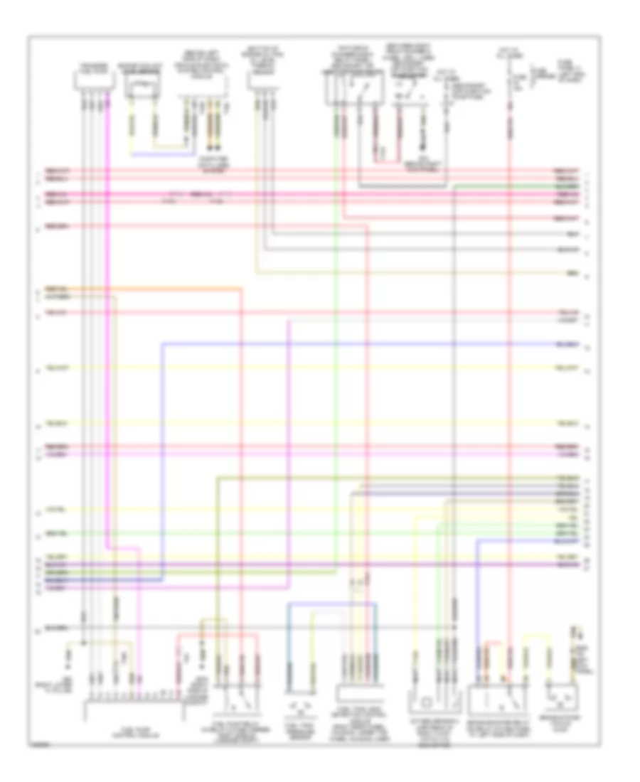
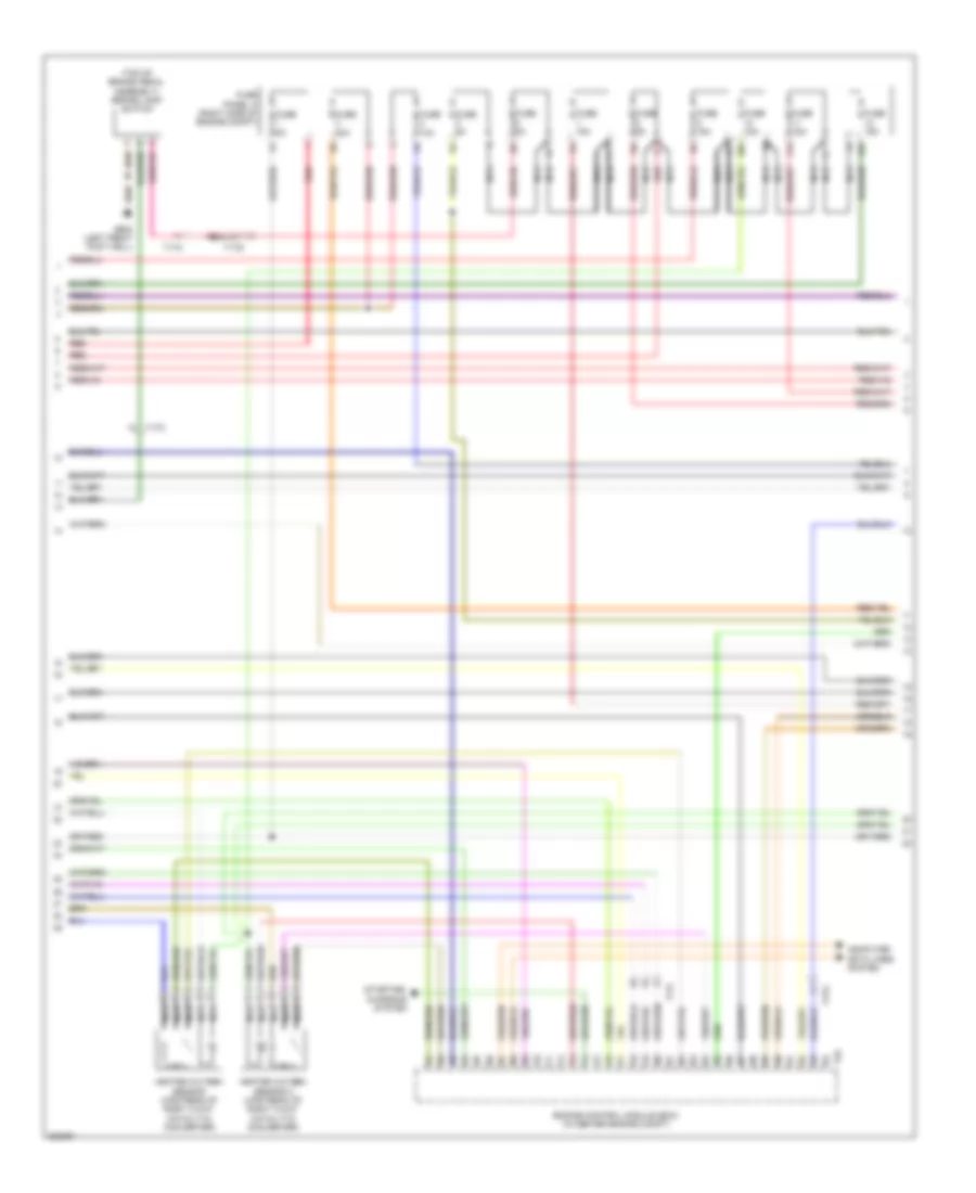
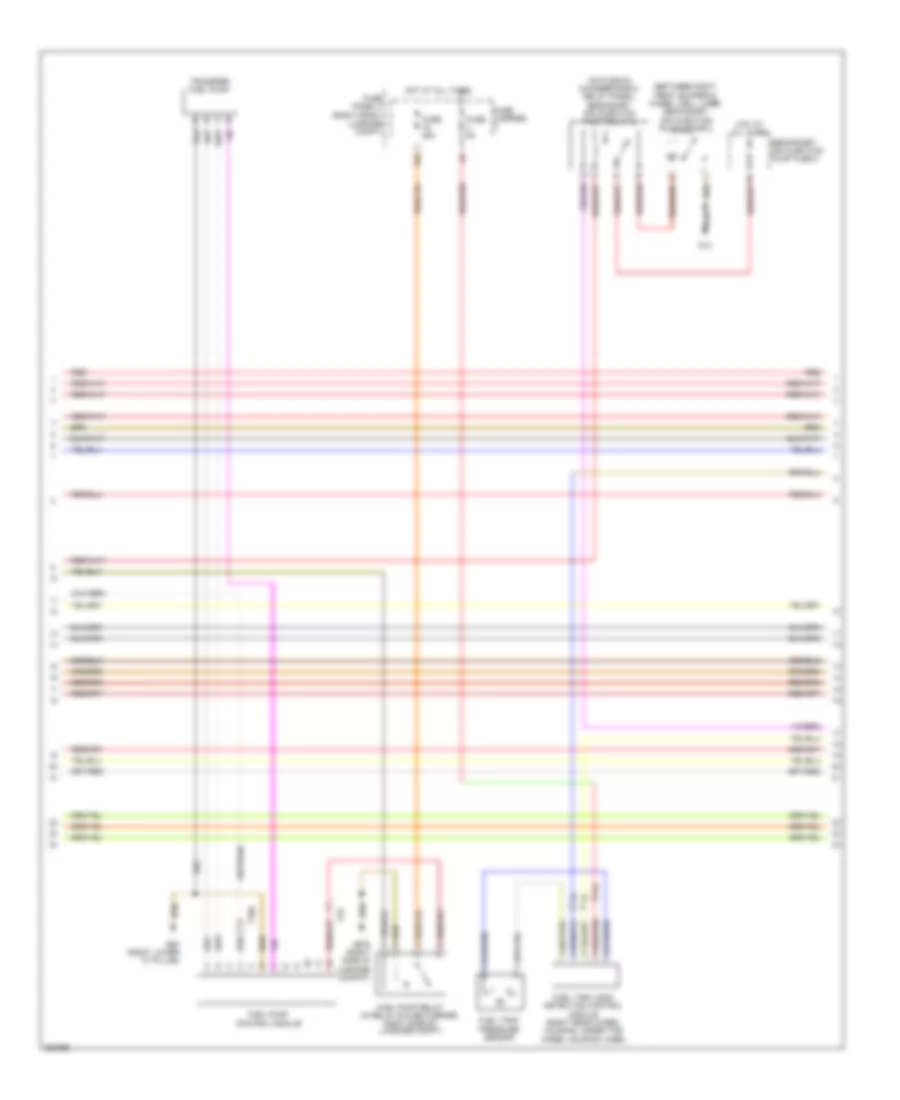
4.2L, Электросхема системы управления двигателем (1 из 7) для Audi A8 L 2012

4.2L, Электросхема системы управления двигателем (1 из 7) для Audi A8 L 2012 - Список элементов:
- (behind right kick panel) g43
- (rear of cylinder bank 1)
- (top of brake pedal assembly) brake lamp switch
- 14a
- 15a
- After-run coolant pump
- Comfort system central control module (right side of luggage compt)
- Cooling fans system
- Electronic power steering system
- Engine control module (ecm) (in center engine compt)
- Fuse 25a
- Fuse 35a
- Fuse 5a
- Fuse carrier
- Fuse panel b (right end of dash)
- Fuse panel f (right front luggage compt)
- G602 (left front foot well)
- G639 (on left kick panel)
- Heated oxygen sensor (upstream of right 3-way catalytic converter)
- Heated oxygen sensor 2 (upstream of right 3-way catalytic converter)
- Hot at all times
- Manifold absolute pressure sensor & intake air temperature sensor
- Nca
- Oxygen sensor (downstream of right 3-way catalytic converter)
- Starting/charging system
- T14b
- T17f
- T17g
- T17k
- T32c
- T91
- Transmissions system
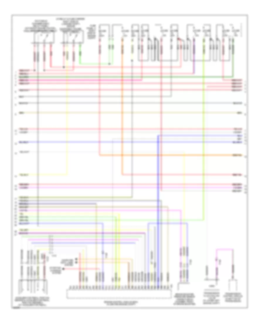
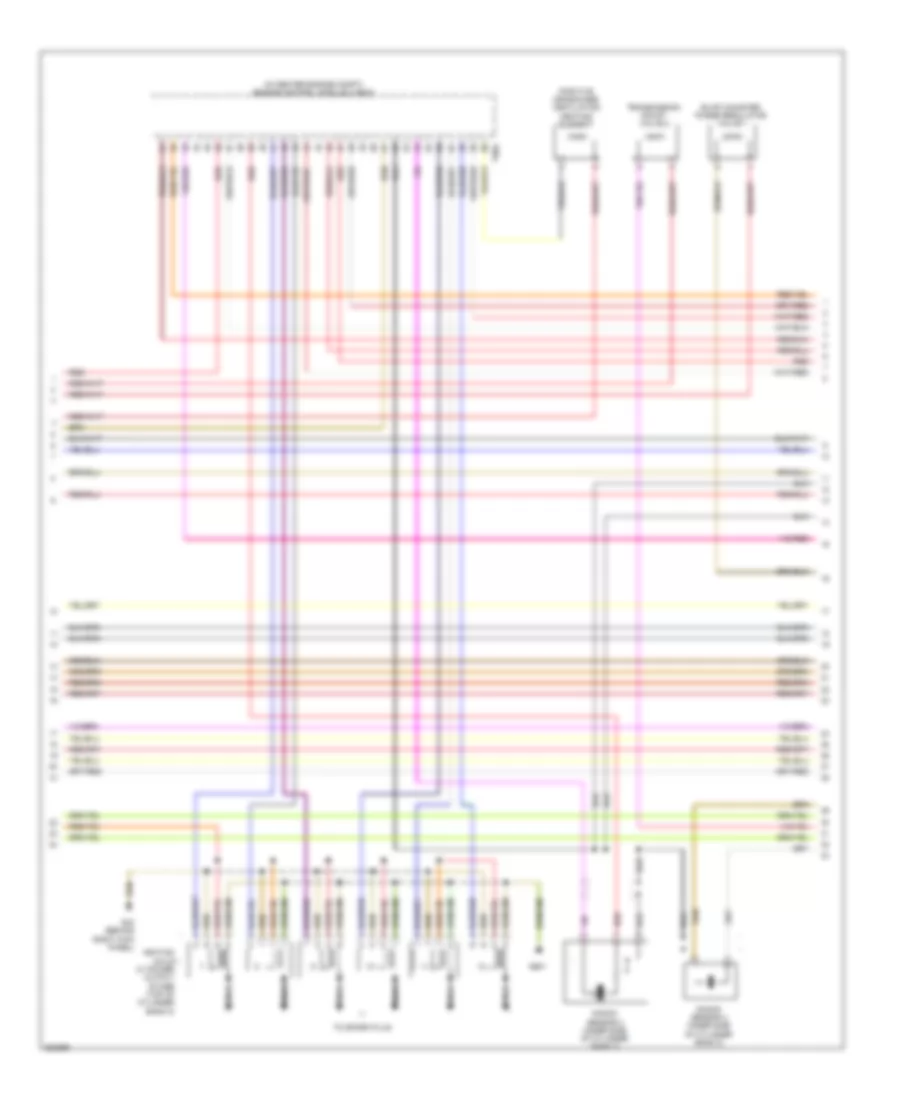
4.2L, Электросхема системы управления двигателем (2 из 7) для Audi A8 L 2012
4.2L, Электросхема системы управления двигателем (2 из 7) для Audi A8 L 2012 - Список элементов:
- (behind left side of dash) vehicle electrical system control module
- (between right front bumper & wheel well liner) secondary air injection pump motor
- (bottom of engine oil pan) oil level thermal sensor
- (on plenum chamber e-box relay panel) secondary air injection pump relay
- 16a
- Brake booster relay (on relay & fuse panel at left side of dash)
- Brake system vacuum pump
- Computer data lines system
- Engine coolant level sensor
- Fuel pump control module
- Fuel pump relay (in relay & fuse carrier, right side of luggage compt)
- Fuel tank leak detection control module (right rear wheel housing, under the wheel housing liner)
- Fuel tank pressure sensor
- Fuse 15a
- Fuse carrier
- Fuse panel c (left end of dash)
- G43 (behind right kick panel)
- G62 (right lower "c" pillar)
- G639 (on left kick panel)
- G675 (right side of luggage compat)
- Hot at all times
- Nca
- Oxygen sensor 2 (upstream of right 3-way catalytic converter)
- Secondary air injection pump fuse
- T10g
- T16c
- T17g
- T17h
- T17k
- T32b
- T3x
- Transfer fuel pump
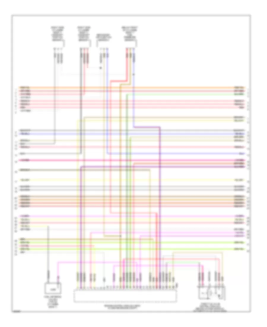
4.2L, Электросхема системы управления двигателем (3 из 7) для Audi A8 L 2012
4.2L, Электросхема системы управления двигателем (3 из 7) для Audi A8 L 2012 - Список элементов:
- 10a
- 11a
- 12a
- Accelerator pedal position sensor & accelerator pedal position sender 2 (at accelerator pedal)
- Brake booster pressure sensor (inside plenum chamber, front of brake booster)
- Computer data lines system
- Engine control module (ecm) (in center engine compt)
- Fuse 10a
- Fuse 15a
- Fuse 30a
- Fuse 5a
- Fuse panel a (right side of engine compt)
- Nca
- Red
- Starting/ charging system
- T14b
- T17f
- T17g
- T17k
- T91
- Transmission control module (in bottom of transmission)
- Transmission fluid cooling valve (in lower left engine compt)
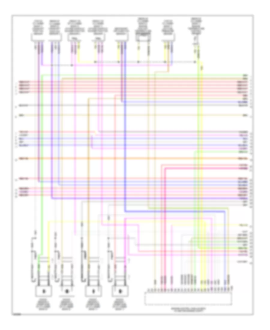
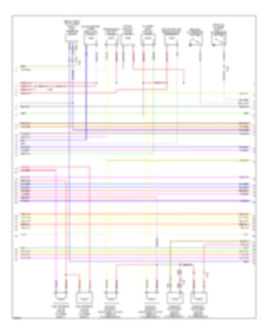
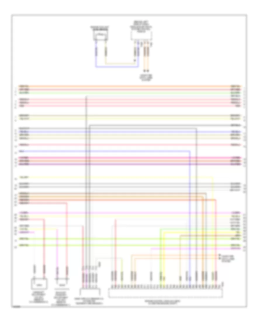
4.2L, Электросхема системы управления двигателем (4 из 7) для Audi A8 L 2012
4.2L, Электросхема системы управления двигателем (4 из 7) для Audi A8 L 2012 - Список элементов:
- (front of cylinder bank 1) intake manifold runner position sensor
- (front of of cylinder bank 2) intake manifold runner position sensor 2
- (rear of cylinder bank 1) engine temperature control sensor
- (rear of cylinder bank 2) camshaft position sensor 4
- (rear of cylinder bank 2) engine coolant temperature (ect) sensor
- (top of cylinder bank 1) camshaft position sensor
- (top of cylinder bank 1) low fuel pressure sensor
- Engine control module (ecm) (in center engine compt)
- Knock sensor 1 (inner side of cylinder bank 1)
- Knock sensor 2 (inner side of cylinder bank 1)
- Knock sensor 3 (inner side of cylinder bank 2)
- Knock sensor 4 (inner side of cylinder bank 2)
- Nca
- Red
- Secondary air injection sensor 1
- T105
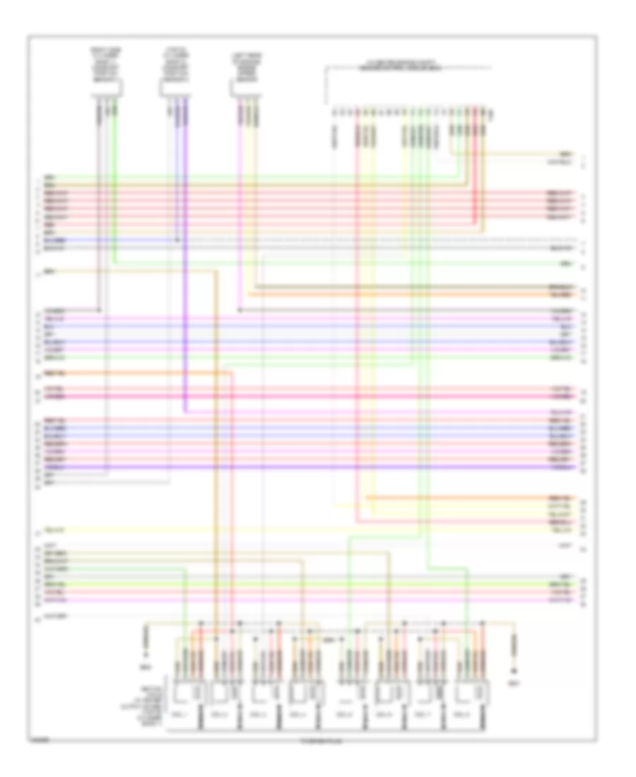
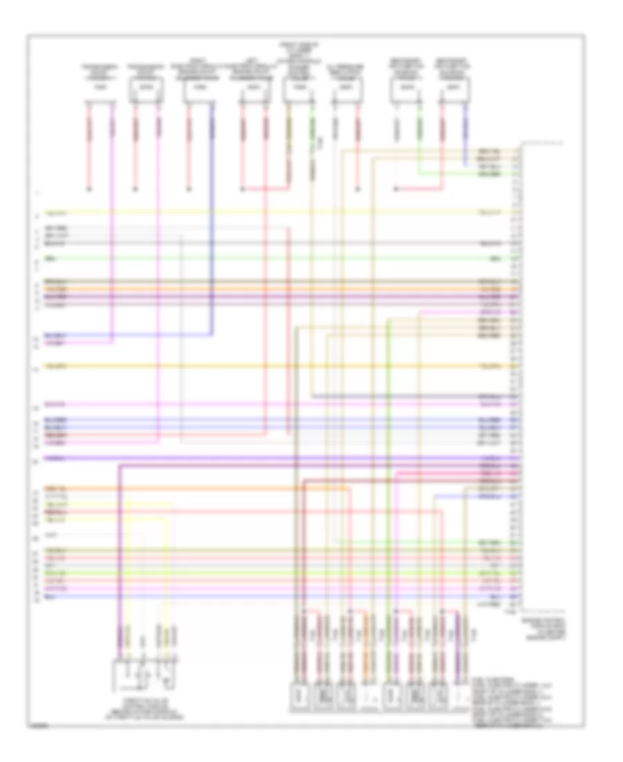
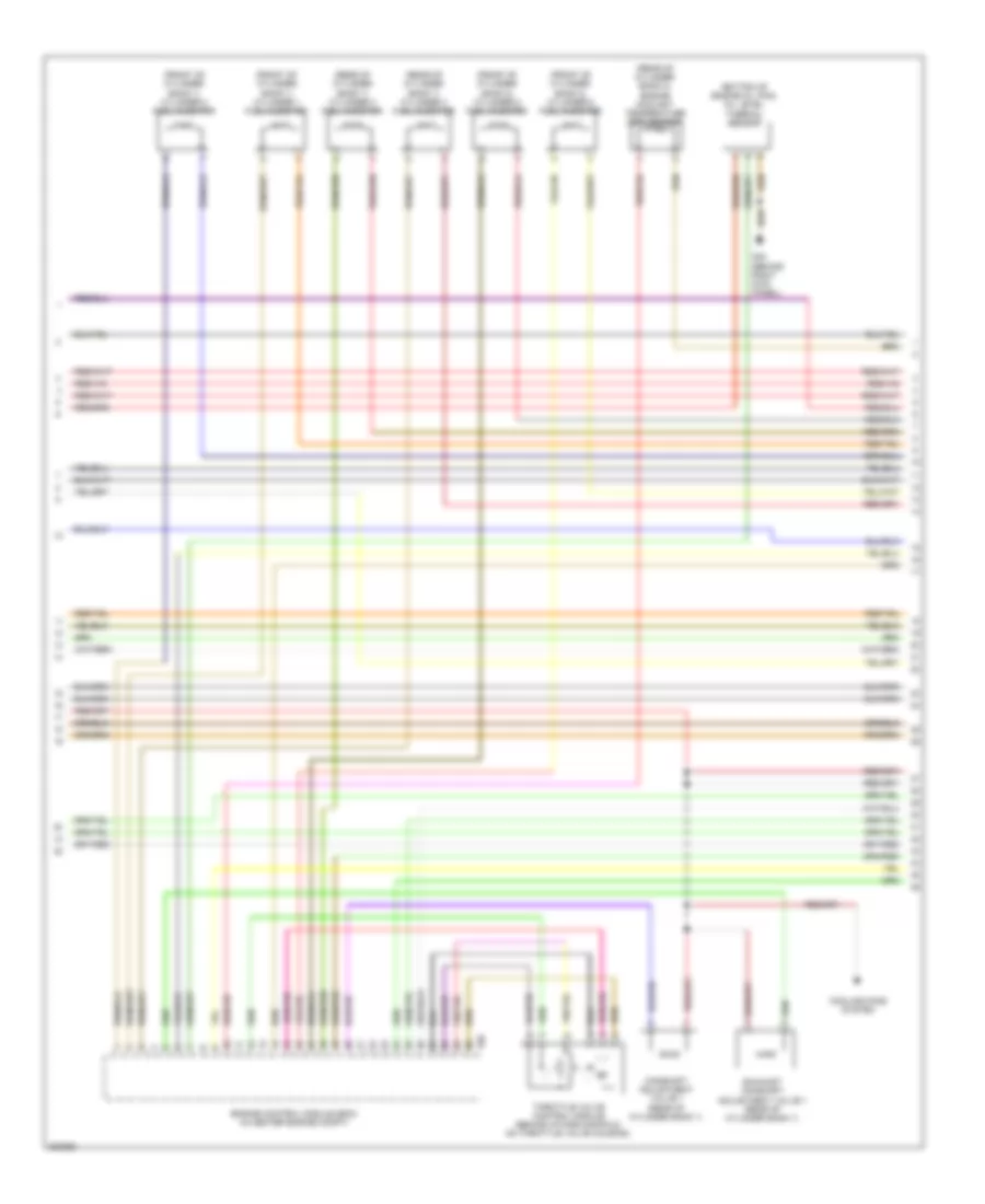
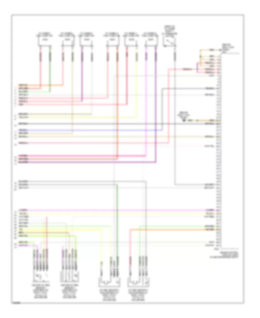
4.2L, Электросхема системы управления двигателем (5 из 7) для Audi A8 L 2012
4.2L, Электросхема системы управления двигателем (5 из 7) для Audi A8 L 2012 - Список элементов:
- (in center engine compt) engine control module (ecm)
- (left rear of engine) engine speed sensor
- (right side cylinder bank 1) camshaft position sensor 3
- (top of cylinder bank 2) camshaft position sensor 2
- Coil 1
- Coil 2
- Coil 3
- Coil 4
- Coil 5
- Coil 6
- Coil 7
- Coil 8
- G600
- G601
- Ignition coils (w/ power output stage) (top of cylinder bank 1)
- Nca
- Red
- T105
- To spark plug
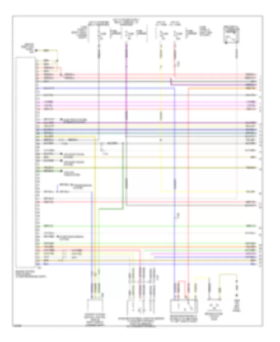
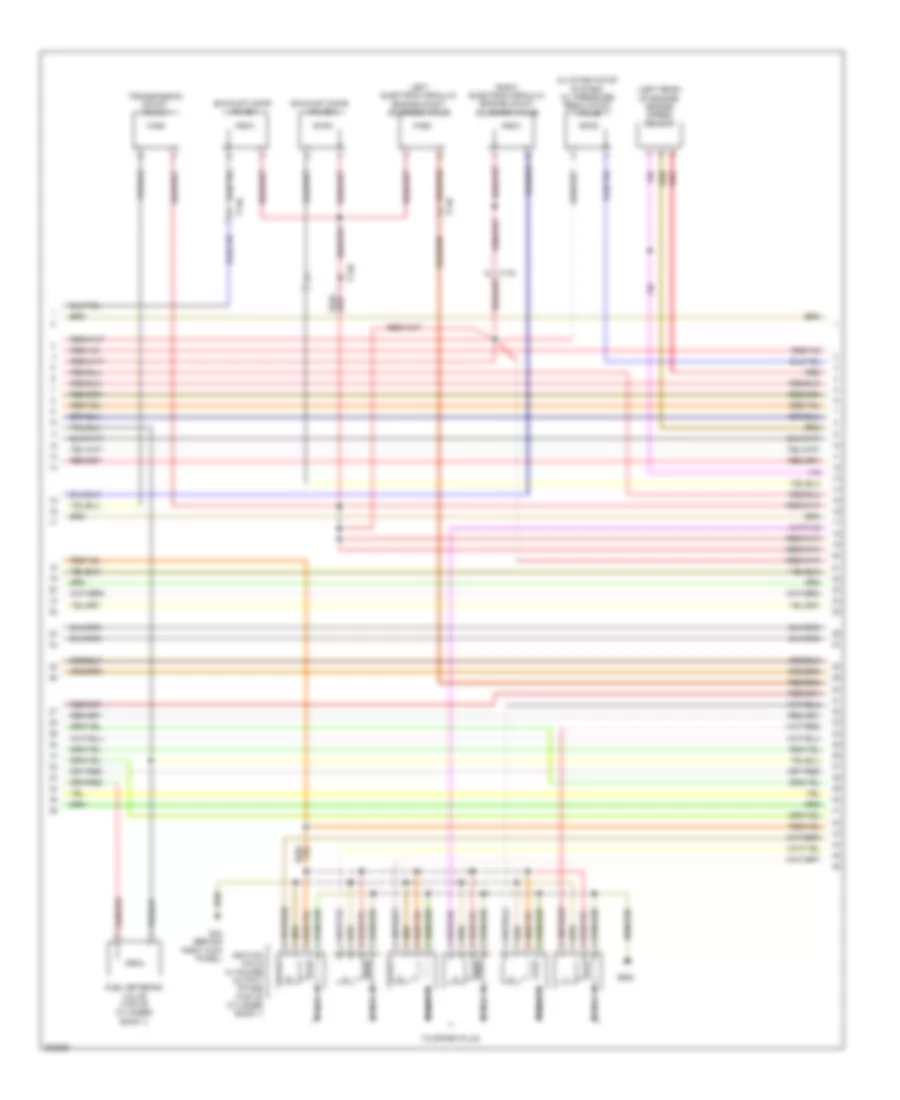
4.2L, Электросхема системы управления двигателем (6 из 7) для Audi A8 L 2012
4.2L, Электросхема системы управления двигателем (6 из 7) для Audi A8 L 2012 - Список элементов:
- (below front of cylinder bank 1) fuel pressure sensor
- (front of cylinder bank 1) oil pressure switch
- Camshaft adjustment valve 1 (rear of cylinder bank 1)
- Camshaft adjustment valve 2 (rear of cylinder bank 2)
- Cylinder head coolant valve
- Evap canister purge regulator valve 1
- Exhaust camshaft adjustment valve 1 (rear of cylinder bank 1)
- Exhaust camshaft adjustment valve 2 (rear of cylinder bank 2)
- Fuel metering valve (top of cylinder bank 1)
- Fuel metering valve 2 (top of cylinder bank 2)
- Intake manifold tuning valve
- Map controlled engine cooling thermostat
- Reduced oil pressure switch
- T14b
- T14c
- T14d
- Transmission coolant valve
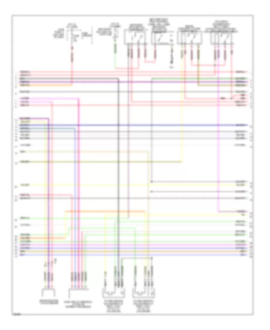
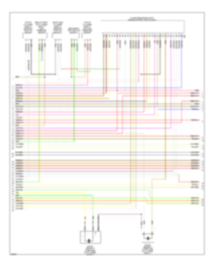
4.2L, Электросхема системы управления двигателем (7 из 7) для Audi A8 L 2012
4.2L, Электросхема системы управления двигателем (7 из 7) для Audi A8 L 2012 - Список элементов:
- (front side of cylinder bank 1) intake manifold runner control valve
- Engine control module (ecm) (in center engine compt)
- Fuel injectors (fuel injector cylinder 1 & 2: front of cylinder bank 1) (fuel injector cylinder 3 & 4: rear of cylinder bank 1) (fuel injector cylinder 5 & 6: front of cylinder bank 2) (fuel injector cylinder 7 & 8:
- Left electrohydraulic engine mount solenoid valve
- Oil pressure regulation valve
- Rear of cylinder bank 2)
- Right electrohydraulic engine mount solenoid valve
- Secondary air injection solenoid valve
- Secondary air injection solenoid valve 2
- T105
- T14c
- T14d
- Throttle valve control module (behind intake manifold, on throttle valve housing)
- Transmission mount valve 1
- Transmission mount valve 2
6.3L
6.3L, Электросхема системы управления двигателем (1 из 11) для Audi A8 L 2012
6.3L, Электросхема системы управления двигателем (1 из 11) для Audi A8 L 2012 - Список элементов:
- (behind right kick panel) g43
- 14a
- Accelerator pedal position sensor & accelerator pedal position sensor 2 (on accelerator pedal)
- Air conditioning system
- Brake booster relay (on relay & fuse panel at left side of dash)
- Brake system vacuum pump
- Comfort system central control module (right side of luggage compt)
- Cooling fans system
- Electronic power steering system
- Engine control module (ecm) (in center engine compt)
- Fuse 35a
- Fuse 5a
- Fuse carrier
- Fuse panel b right end of dash)
- Fuse panel f (right front luggage compt)
- G639 (on left kick panel)
- Hot at all times
- Hot w/ starter relay energized
- Reduced oil oil pressure switch
- Starting/charging system
- T14b
- T17f
- T17g
- T17k
- T32c
- T94
- Transmissions system
6.3L, Электросхема системы управления двигателем (2 из 11) для Audi A8 L 2012
6.3L, Электросхема системы управления двигателем (2 из 11) для Audi A8 L 2012 - Список элементов:
- (between right front bumper & wheel well liner) secondary air injection pump motor
- 16a
- Brake booster vacuum sensor
- Fuse 15a
- Fuse carrier
- Fuse panel c (left end of dash)
- G13
- Hot at all times
- Mass airflow sensor & intake air temperature sensor
- Nca
- Oxygen sensor (downstream of right 3-way catalytic converter)
- Oxygen sensor 2 (downstream of right 3-way catalytic converter)
- Red
- Secondary air injection pump fuse
- Secondary air injection pump relay
- T14b
6.3L, Электросхема системы управления двигателем (3 из 11) для Audi A8 L 2012
6.3L, Электросхема системы управления двигателем (3 из 11) для Audi A8 L 2012 - Список элементов:
- (top of brake pedal assembly) brake lamp switch
- 10a
- 11a
- 12a
- Computer data lines system
- Engine control module (ecm) (in center engine compt)
- Fuse 10a
- Fuse 15a
- Fuse 30a
- Fuse 5a
- Fuse panel a (right side of engine compt)
- G602 (left front foot well)
- Heated oxygen sensor (upstream of right 3-way catalytic converter)
- Heated oxygen sensor 2 (upstream of right 3-way catalytic converter)
- Nca
- Red
- Starting/ charging system
- T17f
- T17g
- T17k
- T94
6.3L, Электросхема системы управления двигателем (4 из 11) для Audi A8 L 2012
6.3L, Электросхема системы управления двигателем (4 из 11) для Audi A8 L 2012 - Список элементов:
- (bottom of engine oil pan) oil level thermal sensor
- (front of cylinder bank 1) cylinder 1 fuel injector
- (front of cylinder bank 1) cylinder 2 fuel injector
- (front of cylinder bank 2) cylinder 5 fuel injector
- (front of cylinder bank 2) cylinder 6 fuel injector
- (rear of cylinder bank 1) cylinder 3 fuel injector
- (rear of cylinder bank 1) cylinder 4 fuel injector
- (rear of cylinder bank 2) engine coolant temperature (ect) sensor
- Camshaft adjustment valve 1 (rear of cylinder bank 1)
- Cooling fans system
- Engine control module (ecm) (in center engine compt)
- Exhaust camshaft adjustment valve 1 (rear of cylinder bank 1)
- G43 (behind right kick panel)
- T60
- Throttle valve control module (behind intake manifold, on throttle valve housing)
6.3L, Электросхема системы управления двигателем (5 из 11) для Audi A8 L 2012
6.3L, Электросхема системы управления двигателем (5 из 11) для Audi A8 L 2012 - Список элементов:
- (left rear of engine) engine speed sensor
- (w/ start/stop system) oil pressure regulation valve
- Exhaust door valve 1
- Exhaust door valve 2
- Fuel metering valve (top of cylinder bank 1)
- G43 (behind right kick panel)
- G600
- Ignition coils w/ power output stage (top of cylinder bank 1)
- Left electrohydraulic engine mount solenoid valve
- Nca
- Red
- Right electrohydraulic engine mount solenoid valve
- T14b
- T17g
- To spark plug
- Transmission mount valve 1
6.3L, Электросхема системы управления двигателем (6 из 11) для Audi A8 L 2012
6.3L, Электросхема системы управления двигателем (6 из 11) для Audi A8 L 2012 - Список элементов:
- (below front of cylinder bank 1) fuel pressure sensor
- (in center engine compt) engine control module (ecm)
- (right side cylinder bank 1) camshaft position sensor 3
- (top of cylinder bank 1) camshaft position sensor
- (top of cylinder bank 1) low fuel pressure sensor
- Knock sensor 1 (inner side of cylinder bank 1)
- Knock sensor 2 (inner side of cylinder bank 1)
- Nca
- Red
- Secondary air injection sensor 1
- T60
6.3L, Электросхема системы управления двигателем (7 из 11) для Audi A8 L 2012
6.3L, Электросхема системы управления двигателем (7 из 11) для Audi A8 L 2012 - Список элементов:
- (between right front bumper & wheel well liner) secondary air injection pump motor 2
- (on plenum chamber e-box relay panel) secondary air injection pump relay 2
- 15a
- Fuel pump control module
- Fuel pump relay (in relay & fuse carrier, right side of luggage compt)
- Fuel tank leak detection control module (right rear wheel housing, under the wheel housing liner)
- Fuel tank pressure sensor
- Fuse 25a
- Fuse 5a
- Fuse carrier
- Fuse panel f (right front luggage compt)
- G13
- G62 (right lower "c" pillar)
- G675 (right side of luggage compat)
- Hot at all times
- Red
- Secondary air injection pump fuse 2
- T10g
- T17g
- T3x
- Transfer fuel pump
6.3L, Электросхема системы управления двигателем (8 из 11) для Audi A8 L 2012
6.3L, Электросхема системы управления двигателем (8 из 11) для Audi A8 L 2012 - Список элементов:
- (in center engine compt) engine control module 2 (ecm)
- Evap canister purge regulator valve 1
- G43 (behind right kick panel)
- G601
- Ignition coils w/ power output stage (top of cylinder bank 2)
- Knock sensor 3 (inner side of cylinder bank 2)
- Knock sensor 4 (inner side of cylinder bank 2)
- Nca
- Positive crankcase ventilation heating element
- Red
- T60a
- To spark plug
- Transmission mount valve 2
6.3L, Электросхема системы управления двигателем (9 из 11) для Audi A8 L 2012
6.3L, Электросхема системы управления двигателем (9 из 11) для Audi A8 L 2012 - Список элементов:
- (below front of cylinder bank 1) fuel pressure sensor 2
- (right side cylinder bank 1) camshaft position sensor 2
- (right side cylinder bank 1) camshaft position sensor 4
- Engine control module 2 (ecm) (in center engine compt)
- Fuel metering valve 2 (top of cylinder bank 1)
- Red
- Secondary air injection sensor 2
- T60a
- Throttle valve control module 2 (behind intake manifold, on throttle valve housing)
6.3L, Электросхема системы управления двигателем (10 из 11) для Audi A8 L 2012
6.3L, Электросхема системы управления двигателем (10 из 11) для Audi A8 L 2012 - Список элементов:
- (behind left side of dash) vehicle electrical system control module
- Camshaft adjustment valve 2 (rear of cylinderbank 2)
- Computer data lines system
- Engine control module 2 (ecm) (in center engine compt)
- Engine coolant level sensor
- Exhaust camshaft adjustment valve 2 (rear of cylinderbank 1)
- Mass airflow sensor 2 & intake air temperature sensor 2
- Red
- T16c
- T32b
- T8ap
- T94a
6.3L, Электросхема системы управления двигателем (11 из 11) для Audi A8 L 2012
6.3L, Электросхема системы управления двигателем (11 из 11) для Audi A8 L 2012 - Список элементов:
- (behind right kick panel) g43
- (front of cylinder bank 1) oil pressure switch
- Cylinder 10 fuel injector
- Cylinder 11 fuel injector
- Cylinder 12 fuel injector
- Cylinder 7 fuel injector
- Cylinder 8 fuel injector
- Cylinder 9 fuel injector
- Engine control module 2 (ecm) (in center engine compt)
- Heated oxygen sensor 3 (upstream of right 3-way catalytic converter)
- Heated oxygen sensor 4 (upstream of right 3-way catalytic converter)
- Nca
- Oxygen sensor 3 (downstream of right 3-way catalytic converter)
- Oxygen sensor 4 (downstream of right 3-way catalytic converter)
- Red
- T94a